2-40 UR FAMILY – COMMUNICATIONS GUIDE
MEMORY MAP CHAPTER 2: MODBUS COMMUNICATION
2
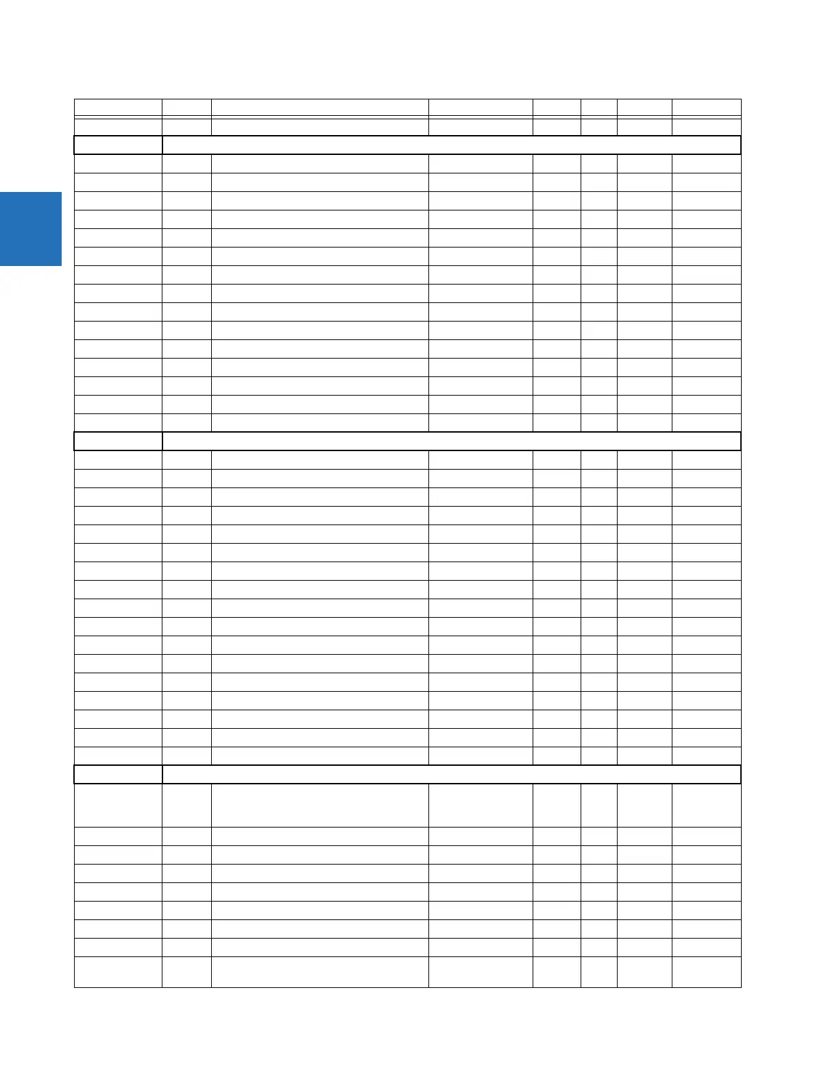
" 24F3 ...Repeated for module 5
Bus Actuals (Read Only) (2 Modules)
B30 2500 Bus Differential IA Magnitude 0 to 999999.999 A 0.001 F060 0
" 2502 Bus Differential IA Angle -359.9 to 0 degrees 0.1 F002 0
" 2503 Bus Differential IB Magnitude 0 to 999999.999 A 0.001 F060 0
" 2505 Bus Differential IB Angle -359.9 to 0 degrees 0.1 F002 0
" 2506 Bus Differential IC Magnitude 0 to 999999.999 A 0.001 F060 0
" 2508 Bus Differential IC Angle -359.9 to 0 degrees 0.1 F002 0
" 2509 Bus Differential Rest IA Magnitude 0 to 999999.999 A 0.001 F060 0
" 250B Bus Differential Rest IA Angle -359.9 to 0 degrees 0.1 F002 0
" 250C Bus Differential Rest IB Magnitude 0 to 999999.999 A 0.001 F060 0
" 250E Bus Differential Rest IB Angle -359.9 to 0 degrees 0.1 F002 0
" 250F Bus Differential Rest IC Magnitude 0 to 999999.999 A 0.001 F060 0
" 2511 Bus Differential Rest IC Angle -359.9 to 0 degrees 0.1 F002 0
" 2515 Bus Maximum CT Primary 0 to 50000 --- 1 F060 1
" 2517 Reserved (9 items) --- --- --- F001 0
" 2520 ...Repeated for Bus 2
RxGOOSE DPS (Read/Write Setting) (16 Modules)
All 2548 RxGOOSE DPS 1 Events 0 to 1 --- 1 F102 0 (Disabled)
" 2549 RxGOOSE DPS 1 Default State 0 to 4 --- 1 F605 4 (Latest)
" 254A ... Repeated for DPS 2
" 254C ... Repeated for DPS 3
" 254E ... Repeated for DPS 4
" 2550 ... Repeated for DPS 5
" 2552 ... Repeated for DPS 6
" 2554 ... Repeated for DPS 7
" 2556 ... Repeated for DPS 8
" 2558 ... Repeated for DPS 9
" 255A ... Repeated for DPS 10
" 255C ... Repeated for DPS 11
" 255E ... Repeated for DPS 12
" 2560 ... Repeated for DPS 13
" 2562 ... Repeated for DPS 14
" 2564 ... Repeated for DPS 15
" 2566 ... Repeated for DPS 16
Phasor Measurement Unit Actual Values (Read Only) (1, 2, or 6 Modules)
C60, D60, F60,
G60, L30, L90,
N60, T60
256D PMU 1 Phase A Voltage Magnitude 0 to 999999.999 V 0.001 F060 0
" 256F PMU Unit 1 Phase A Voltage Angle -180 to 180 ° 0.01 F002 0
" 2570 PMU 1 Phase B Voltage Magnitude 0 to 999999.999 V 0.001 F060 0
" 2572 PMU 1 Phase B Voltage Angle -180 to 180 ° 0.01 F002 0
" 2573 PMU 1 Phase C Voltage Magnitude 0 to 999999.999 V 0.001 F060 0
" 2575 PMU 1 Phase C Voltage Angle -180 to 180 ° 0.01 F002 0
" 2576 PMU 1 Auxiliary Voltage Magnitude 0 to 999999.999 V 0.001 F060 0
" 2578 PMU 1 Auxiliary Voltage Angle -180 to 180 ° 0.01 F002 0
" 2579 PMU 1 Positive Sequence Voltage
Magnitude
0 to 999999.999 V 0.001 F060 0
Products Address Register name Range Units Step Format Default

 Loading...


