5-8 170 Series Monitor Revision C
2000947-004
Theory of Operation: Functional Overview
* Active low.
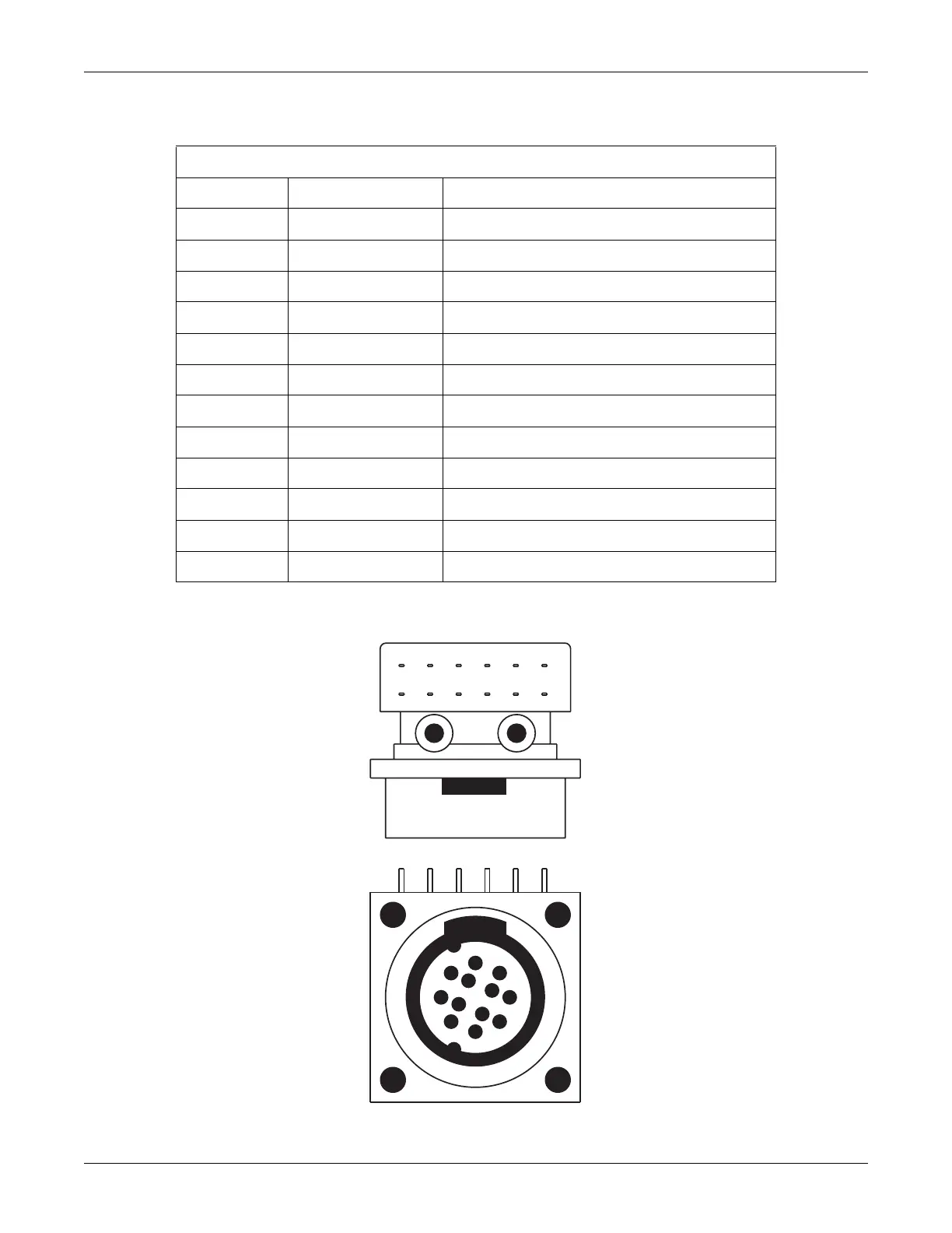
Figure 5-5. US Connector(s) (facing the front panel from the outside)
Table 5-9. Ultrasound Connector(s)
Pin # Signal Name Signal Description
1 NC No Connection
2 NC No Connection
3 GND Chassis Ground
4 XMIT/RCV SHIELD Shield for Transmit/Receive
5 XMIT/RCV Transmit/Receive
6 NC No Connection
7 NC No Connection
8 NC No Connection
9 GND Chassis Ground
10 NC No Connection
11 U/S ENABLE* Enable for Ultrasound Channel
12 GND Chassis Ground
1
2
3
4
5
6
7
12
9
8
10
11
23
4
56
879
101112
1
 Loading...