Revision C 170 Series Monitor 5-31
2000947-004
Theory of Operation: Main Board Theory of Operation
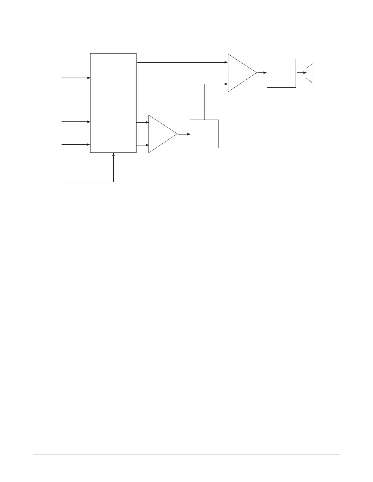
Figure 5-18. Audio Module Block Diagram
Ultrasound Envelopes
The outputs of the main filters are also input to U32 and U35. The input to U35 is
through high-pass filters at 63 Hz. The high pass components for Channel 1 and
Channel 2 are C154/R338 and C159/R357, respectively. The output of the main
filters are also input to U32; this integrated circuit, in conjunction with U35, forms
an AGC (automatic gain control) circuit for both ultrasound channels.
Each of these AGC circuit has a maximum gain of 200 with a dynamic range of 46
dB. Each of the AGC outputs are high-pass filtered by
C169/R343 at 90 Hz with a gain of one, then input to a half-wave detector U36 (pin
7) with a gain of 1.47. The output of the detector circuits are low-pass filtered by
U36 (pin 1)at 20 Hz at gain of ten.
These envelopes are then input to the analog-to-digital converter U38. Other inputs
to the analog-to-digital converter are the telemetry TOCO signal. This signal is
scaled and offset to provide –100 to +400 relative UA units.
Digital
Potentiometers
for Volume
Control (x3)
Ultrasound
Audio
Doubler
Bridge
Amplifier
Summing
Amplifier
Summing
Amplifier
Tone Bit
Channel 1
US Audio
Channel 2
US Audio
Serial Clock and Data
 Loading...