5-32 170 Series Monitor Revision C
2000947-004
Theory of Operation: Main Board Theory of Operation
Uterine Activity
Integrated circuit U33, with a gain of 200, and U34 (pin 7), with a gain of 1.25,
provide a total gain of 250 for the on-board tocotransducer pressure channel. The
output of U34 (pin 7) is offset +0.5 V, providing a dynamic range of –80 to +400
relative units. Each relative unit represents 20 µV at the input of U33 through
resistors R318 and R320.
Integrated circuit U42, and its associated components, comprise a charge pump that
converts the +3.3 V to –3.3 V. U38 (pin 11) and U34 (pin 1) comprise a 2.5 V
reference voltage. U71 (pin 7) provides a reference voltage which is half the 2.5 V
reference, called VREF/2. Integrated circuit U56 (pin 7), and associated
components, provides the +4 V required for the tocotransducer.
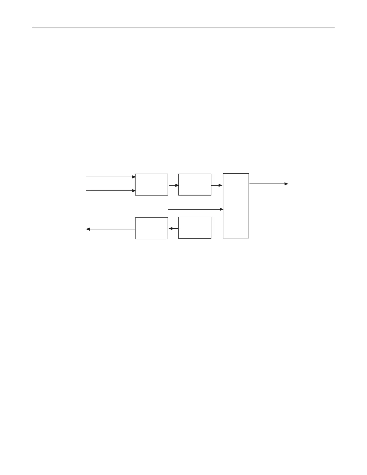
Figure 5-19 provides a block diagram of the antepartum uterine activity section.
Figure 5-19. Antepartum UA Module Block Diagram
Gain
Stage
Differential
Amplifier
+4 V
Reference
Amplifier
A/D
Pressure
to Data Bus
+2.5 V
Reference
Pressure
Telemetry TOCO
+4 V Reference
 Loading...