5-250 D60 Line Distance Protection System GE Multilin
5.6 GROUPED ELEMENTS 5 SETTINGS
5
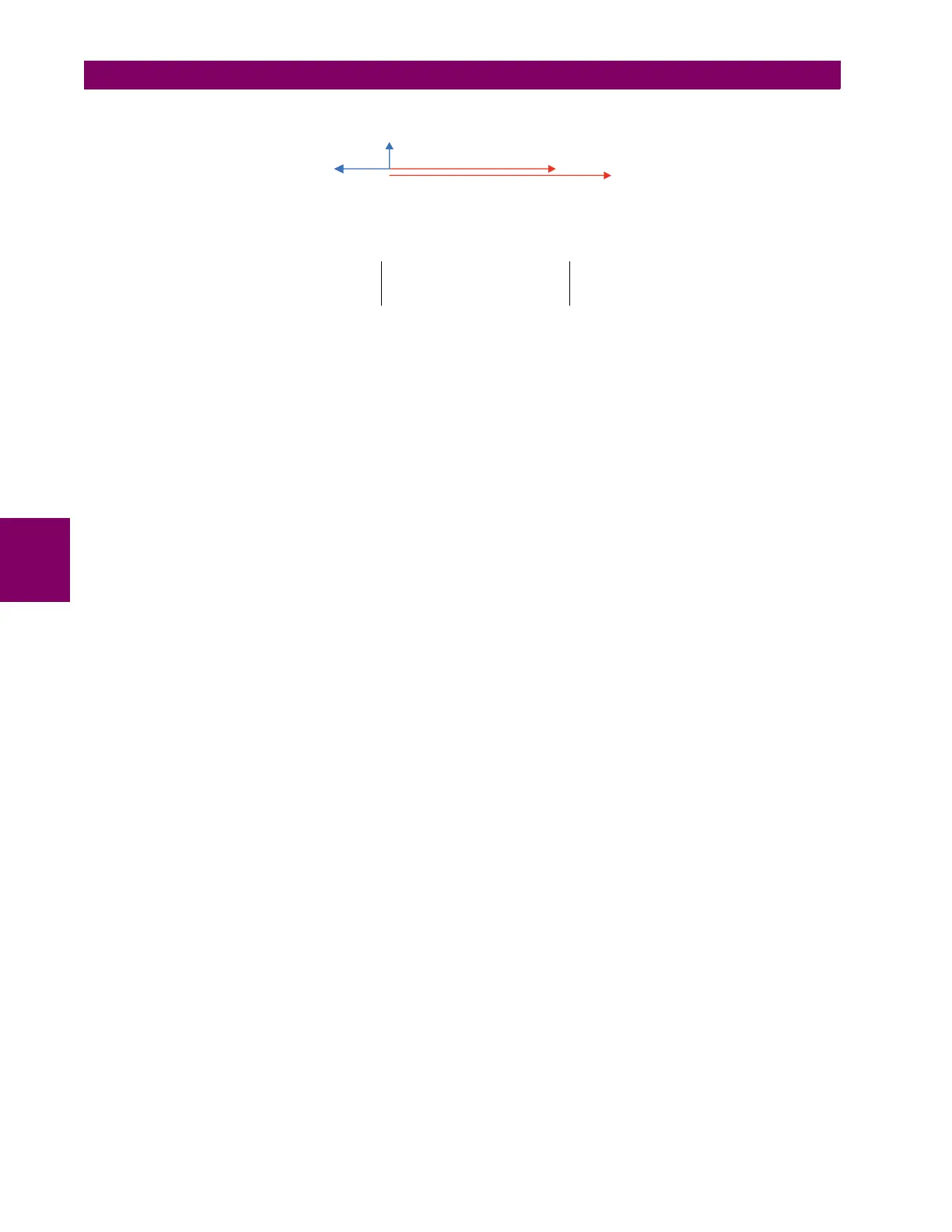
Figure 5–127: PHASOR DIAGRAM
The function approximates the voltage rise at the far end of the transmission line according to the following relationship:
(EQ 5.23)
In the above equation:
• V_1 is the positive-sequence voltage (phasor quantity) in secondary volts measured at the local terminal.
• I_1 is the positive-sequence current (phasor quantity) in secondary amps measured at the local terminal.
• V
nominal
is the phase VT secondary setting in the case of wye VTs and the phase VT secondary setting dividec by √3 in
the case of delta VTs.
• Z
C_mag
and Z
C_ang
represent an impedance between the local and remote terminals.
• V_1
C
is the calculated positive-sequence voltage magnitude at the remote terminal.
If the magnitude of Z
C
is set to one-half the series impedance of the line (R + jX
L
), the compensated voltage will be approx-
imately equal to the positive-sequence voltage at the remote end of the line. A more accurate setting of Z
C
may be made if
the positive-sequence charging current and the voltages at the local and remote line ends resulting from an open breaker
are known. In this case, the desired reach setting would be:
(EQ 5.24)
The following settings are available.
• COMPENSATED OV Zc MAG: This setting specifies the magnitude of the impedance Z
C
in secondary ohms. This
should be set to half the positive-sequence series impedance of the line. Alternately, if the positive-sequence charging
currents and local and remote voltages are known, then this value can be calculated from equation above.
• COMPENSATED OV Zc ANG: This setting specifies the angle of the impedance Z
C
in degrees.
• COMPENSATED OV I_1max: This setting specifies the maximum expected positive-sequence line current for which a
remote overvoltage is anticipated.
• COMPENSATED OV STG1 PKP, COMPENSATED OV STG2 PKP, COMPENSATED OV STG3 PKP: These settings
specify the pickup level for each of the three stages. If any stage is set with no intentional time delay, then the pickup
setting should be set 15% above the anticipated steady state overvoltage to prevent an operation during line energiza-
tion. A stage that is not used may be set to its maximum setting value (3.000 pu) to effectively disable it.
• COMPENSATED OV STG1 DELAY, COMPENSATED OV STG2 DELAY, COMPENSATED OV STG3 DELAY: These
settings specify the time delay for each of the three stages in seconds.
The compensated overvoltage scheme logic is shown below.
843811A1.CDR
V_1
V_1
c
I_1
I_1 × Z
c
V_1
C
pu
V_1 I_1 Z
C_mag
e
jZ
C_ang
–
V
nominal
-------------------------------------------------------------------------------
=
Z
C
V
local
V
remote
–
I
ch earg
----------------------------------------
=