8-6 D60 Line Distance Protection System GE Multilin
8.1 DISTANCE ELEMENTS 8 THEORY OF OPERATION
8
8.1.4 MEMORY POLARIZATION
All distance functions use memory polarization. The positive-sequence voltage – either memorized or actual – is used as a
polarizing signal. The memory is established when the positive-sequence voltage remains above 80% of its nominal value
for five power system cycles. The memory voltage is a two-cycle old voltage.
Once established, the memory is applied for the user-specified time interval. The memory timer is started when the voltage
drops below 80% of nominal or when the user-programmable condition is asserted to force memory polarization. After the
memory expires, the relay checks the magnitude of the actual positive-sequence voltage. If it is higher than 10% of nomi-
nal, the actual voltage is used; if lower, the memory voltage continues to be used.
A provision is added to force self-polarization from any user-programmable condition.
The memory-polarized mho has an extra directional integrity built-in as illustrated below. The self-polarized mho character-
istic is shifted in the reverse direction for a forward fault by an amount proportional to the source impedance, and in the for-
ward direction for a reverse fault.
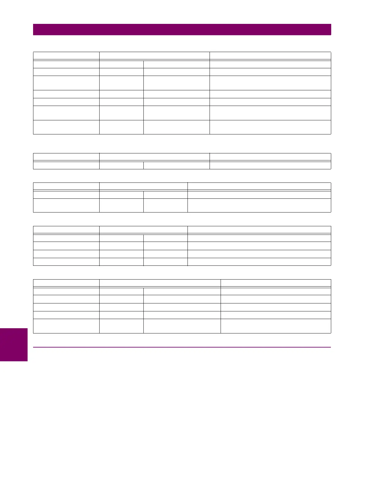
Table 8–4: DIRECTIONAL QUADRILATERAL GROUND DISTANCE FUNCTIONS
CHARACTERISTIC COMPARATOR INPUTS LIMIT ANGLE
Reactance I Z – V j I_0 e
j
or j I_2 e
j
COMP LIMIT
Directional I_0 Z
D
V_1M DIR COMP LIMIT
Directional I_2 Z
D
V_1M DIR COMP LIMIT (removed when 3I_0 > OC SUPV
and I_2 < CUTOFF)
Right Blinder I Z
R
– V I Z
R
90°
Left Blinder I Z
L
– V I Z
L
90°
Fault-type I_0 I_2 50° (removed during open pole conditions or when
3I_0 > OC SUPV and I_2 < CUTOFF)
Zero-sequence I_0 Z
D
–V_0 90° (zones and higher only; removed for zones 2 and
higher during open pole conditions)
Table 8–5: NON-DIRECTIONAL MHO PHASE DISTANCE FUNCTIONS
CHARACTERISTIC COMPARATOR INPUTS LIMIT ANGLE
Offset mho I Z – V V-I Z
REV
COMP LIMIT
Table 8–6: NON-DIRECTIONAL MHO GROUND DISTANCE FUNCTIONS
CHARACTERISTIC COMPARATOR INPUTS LIMIT ANGLE
Offset mho I Z – V V-I Z
REV
COMP LIMIT
Fault-type I_0 I_2 50° (removed during open pole conditions or when 3I_0 > OC
SUPV and I_2 < CUTOFF)
Table 8–7: NON-DIRECTIONAL QUADRILATERAL PHASE DISTANCE FUNCTIONS
CHARACTERISTIC COMPARATOR INPUTS LIMIT ANGLE
Forward Reactance I Z – V I ZCOMP LIMIT
Reverse Reactance I Z
REV
– V I Z
REV
COMP LIMIT
Right Blinder I Z
R
– V I Z
R
90°
Left Blinder I Z
L
– V I Z
L
90°
Table 8–8: NON-DIRECTIONAL QUADRILATERAL GROUND DISTANCE FUNCTIONS
CHARACTERISTIC COMPARATOR INPUTS LIMIT ANGLE
Forward Reactance I Z – V j I_0 e
j
or j I_2 e
j
COMP LIMIT
Reverse Reactance I Z
REV
– V –j I_0 e
j
or –j I_2 e
j
COMP LIMIT
Right Blinder I Z
R
– V I Z
R
90°
Left Blinder I Z
L
– V I Z
L
90°
Fault-type I_0 I_2 50° (removed during open pole conditions or
when 3I_0 > OC SUPV and I_2 < CUTOFF)