GE Multilin D60 Line Distance Protection System 8-5
8 THEORY OF OPERATION 8.1 DISTANCE ELEMENTS
8
j) FAULT-TYPE CHARACTERISTIC
The fault-type characteristic applies to ground elements only and is achieved by checking the angle between:
A ground element: I_0 and I
A
_2;
B ground element: I_0 and I
B
_2
C ground element: I_0 and I
C
_2
The limit angle of the comparator is not adjustable and equals 50°. The fault-type characteristic is intended to block the
ground distance elements during double-line-to-ground faults.
k) ZERO-SEQUENCE DIRECTIONAL CHARACTERISTIC
The extra zero-sequence characteristic applies to ground zones 2 and higher and is achieved by checking angles between:
A ground element: I_0 Z
D
and –V_0
B ground element: I_0 Z
D
and –V_0
C ground element: I_0 Z
D
and –V_0
The limit angle of the comparator is not adjustable and equals 90°. The zero-sequence directional characteristic improves
directional integrity for time-delayed operations after the memory expires.
l) OVERCURRENT SUPERVISION
The overcurrent supervision responds to the following currents:
AB phase element: (I
A
– I
B
)/
BC phase element: (I
B
– I
C
)/
CA phase element: (I
C
– I
A
)/
A, B, C ground element: | 3 I_0 – 0.05 × I_1 |
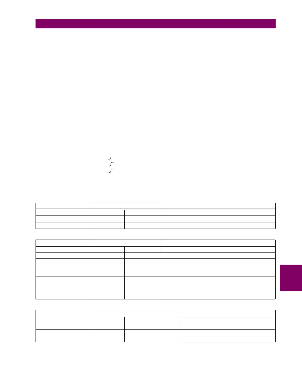
The following tables summarize the characteristics of the distance elements
Table 8–1: DIRECTIONAL MHO PHASE DISTANCE FUNCTIONS
CHARACTERISTIC COMPARATOR INPUTS LIMIT ANGLE
Variable mho I Z – V V_1M COMP LIMIT
Reactance I Z – V I ZCOMP LIMIT
Directional I Z
D
V_1M DIR COMP LIMIT
Table 8–2: DIRECTIONAL MHO GROUND DISTANCE FUNCTIONS
CHARACTERISTIC COMPARATOR INPUTS LIMIT ANGLE
Variable mho I Z – V V_1M COMP LIMIT
Reactance I Z – V I_0 ZCOMP LIMIT
Directional I_0 Z
D
V_1M DIR COMP LIMIT
Directional I_2 Z
D
V_1M DIR COMP LIMIT (removed when 3I_0 > OC SUPV and
I_2 < CUTOFF)
Fault-type I_0 I_2 50° (removed during open pole conditions or when 3I_0 > OC
SUPV and I_2 < CUTOFF)
Zero-sequence I_0 Z
D
–V_0 90° (zones 2 and higher only; removed for zones 2 and higher
during open pole conditions)
Table 8–3: DIRECTIONAL QUADRILATERAL PHASE DISTANCE FUNCTIONS
CHARACTERISTIC COMPARATOR INPUTS LIMIT ANGLE
Reactance I Z – V I ZCOMP LIMIT
Directional I Z
D
V_1M DIR COMP LIMIT
Right Blinder I Z
R
– V I Z
R
90°
Left Blinder I Z
L
– V I Z
L
90°