5-314 D60 Line Distance Protection System GE Multilin
5.7 CONTROL ELEMENTS 5 SETTINGS
5
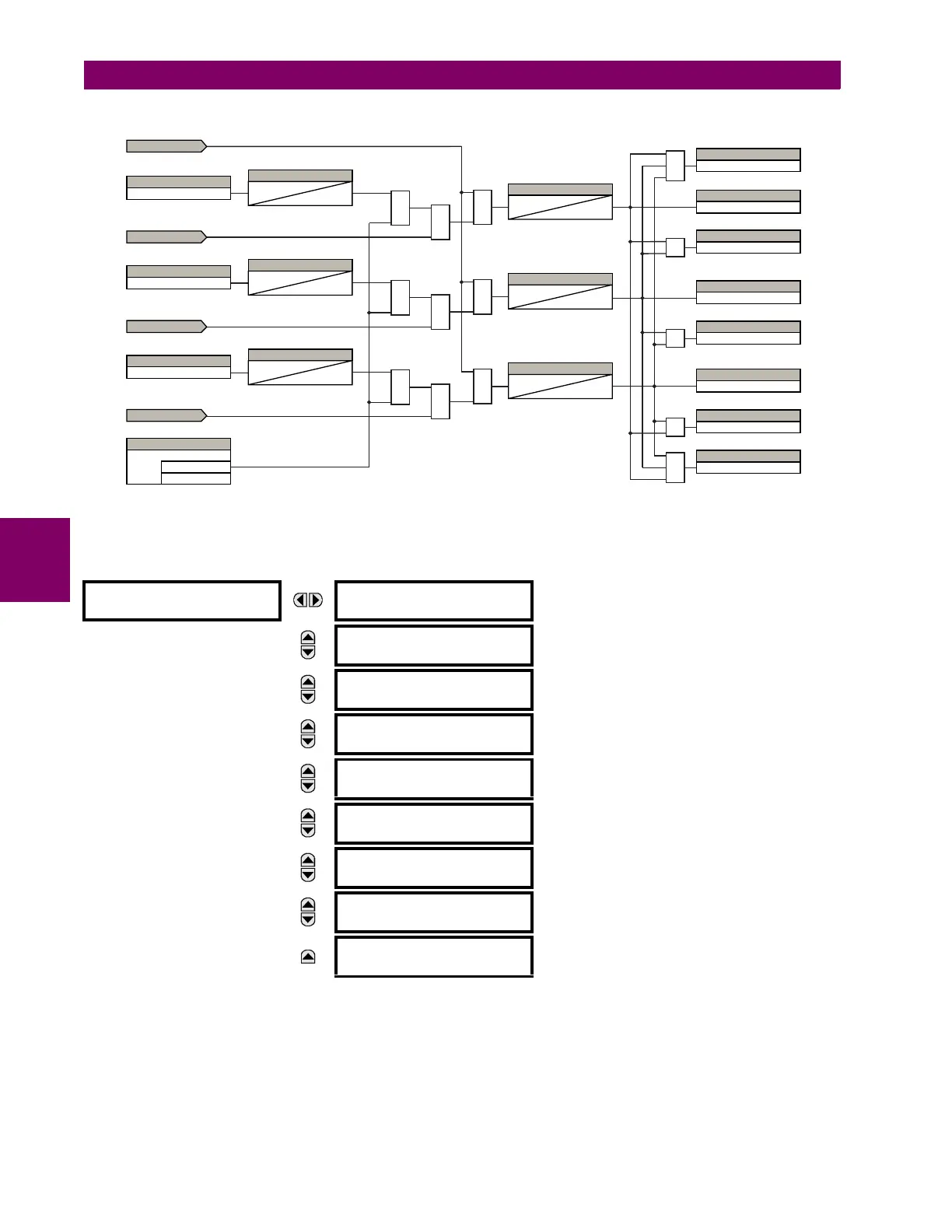
Figure 5–161: OPEN POLE DETECTOR LOGIC (Sheet 2 of 2)
g) BROKEN CONDUCTOR DETECTION
PATH: SETTINGS CONTROL ELEMENTS MONITORING ELEMENTS BROKEN CONDUCTOR 1(2)
Two broken conductor detection elements are provided.
The broken conductor function will detect a transmission line broken conductor condition or a single-pole breaker malfunc-
tion condition through checking the phase current input signals and the I_2 / I_1 ratio. The intention of this function is to
detect a single-phase broken conductor only. As such two-phase or three-phase broken conductors cannot be detected.
BROKEN CONDUCTOR 1
BROKEN CONDUCTOR 1
FUNCTION: Disabled
Range: Disabled, Enabled
MESSAGE
BROKEN CONDUCTOR 1
SOURCE: SRC 1
Range: SRC 1, SRC 2, SRC 3, SRC 4
MESSAGE
BROKEN CONDUCTOR 1
I2/I1 RATIO: 20%
Range: 20.0% to 100.0% in steps of 0.1%
MESSAGE
BROKEN CONDUCTOR 1
I1 MIN: 0.10 pu
Range: 0.05 to 1.00 pu in steps of 0.01
MESSAGE
BROKEN CONDUCTOR 1
I1 MAX: 1.50 pu
Range: 0.05 to 5.00 pu in steps of 0.01
MESSAGE
BROKEN CONDUCTOR 1
PKP DELAY: 20.000 s
Range: 0.000 to 65.535 s in steps of 0.001
MESSAGE
BROKEN CONDCT 1 BLK:
Off
Range: FlexLogic operand
MESSAGE
BROKEN CONDUCT 1
TARGET: Self-reset
Range: Self-reset, Latched, Disabled
MESSAGE
BROKEN CONDUCT 1
EVENTS: Disabled
Range: Disabled, Enabled
OR
837038A2.CDR
OR
OR
OR
OR
XOR
FLEXLOGIC OPERAND
TRIP PHASE A
PHASE A
TIMER
0.5 cycles
0
ENABLED
from the trip output element
OR
FLEXLOGIC OPERAND
TRIP PHASE B
PHASE B
TIMER
0.5 cycles
0
from the trip output element
OR
FLEXLOGIC OPERAND
TRIP PHASE C
PHASE C
TIMER
0.5 cycles
0
from the trip output element
AND
AND
AND
TIMER
0
20 ms
TIMER
0
20 ms
TIMER
0
20 ms
FLEXLOGIC OPERAND
OPEN POLE BLK N
FLEXLOGIC OPERAND
OPEN POLE OP AΦ
FLEXLOGIC OPERAND
OPEN POLE BLK AB
FLEXLOGIC OPERAND
OPEN POLE OP BΦ
FLEXLOGIC OPERAND
OPEN POLE BLK BC
FLEXLOGIC OPERAND
OPEN POLE OP CΦ
FLEXLOGIC OPERAND
OPEN POLE BLK CA
FLEXLOGIC OPERAND
OPEN POLE OP
AND
AND
AND
from open pole logic sheet 1
from open pole logic sheet 1
from open pole logic sheet 1
from open pole logic sheet 1
SETTING
= Accelerated
= Traditional
Open Pole Mode