2-18 D60 Line Distance Protection System GE Multilin
2.3 SPECIFICATIONS 2 PRODUCT DESCRIPTION
2
GROUND DISTANCE
Characteristic: Mho (memory polarized or offset) or
Quad (memory polarized or non-direc-
tional), selectable individually per zone
Reactance polarization: negative-sequence or zero-sequence
current
Non-homogeneity angle: –40 to 40° in steps of 1
Number of zones: 5
Directionality: forward, reverse, or non-directional per
zone
Reach (secondary ): 0.02 to 500.00 in steps of 0.01
Reach accuracy: ±5% including the effect of CVT tran-
sients up to an SIR of 30
Distance characteristic angle: 30 to 90° in steps of 1
Distance comparator limit angle: 30 to 90° in steps of 1
Directional supervision:
Characteristic angle: 30 to 90° in steps of 1
Limit angle: 30 to 90° in steps of 1
Zero-sequence compensation
Z0/Z1 magnitude: 0.00 to 10.00 in steps of 0.01
Z0/Z1 angle: –90 to 90° in steps of 1
Zero-sequence mutual compensation
Z0M/Z1 magnitude: 0.00 to 7.00 in steps of 0.01
Z0M/Z1 angle: –90 to 90° in steps of 1
Right blinder (Quad only):
Reach: 0.02 to 500 in steps of 0.01
Characteristic angle: 60 to 90° in steps of 1
Left blinder (Quad only):
Reach: 0.02 to 500 in steps of 0.01
Characteristic angle: 60 to 90° in steps of 1
Time delay: 0.000 to 65.535 s in steps of 0.001
Timer accuracy: ±3% of operate time or ±1/4 cycle
(whichever is greater)
Current supervision:
Level: neutral current (3I_0)
Pickup: 0.050 to 30.000 pu in steps of 0.001
Dropout: 97 to 98%
Memory duration: 5 to 25 cycles in steps of 1
Voltage supervision pickup (series compensation applications):
0 to 5.000 pu in steps of 0.001
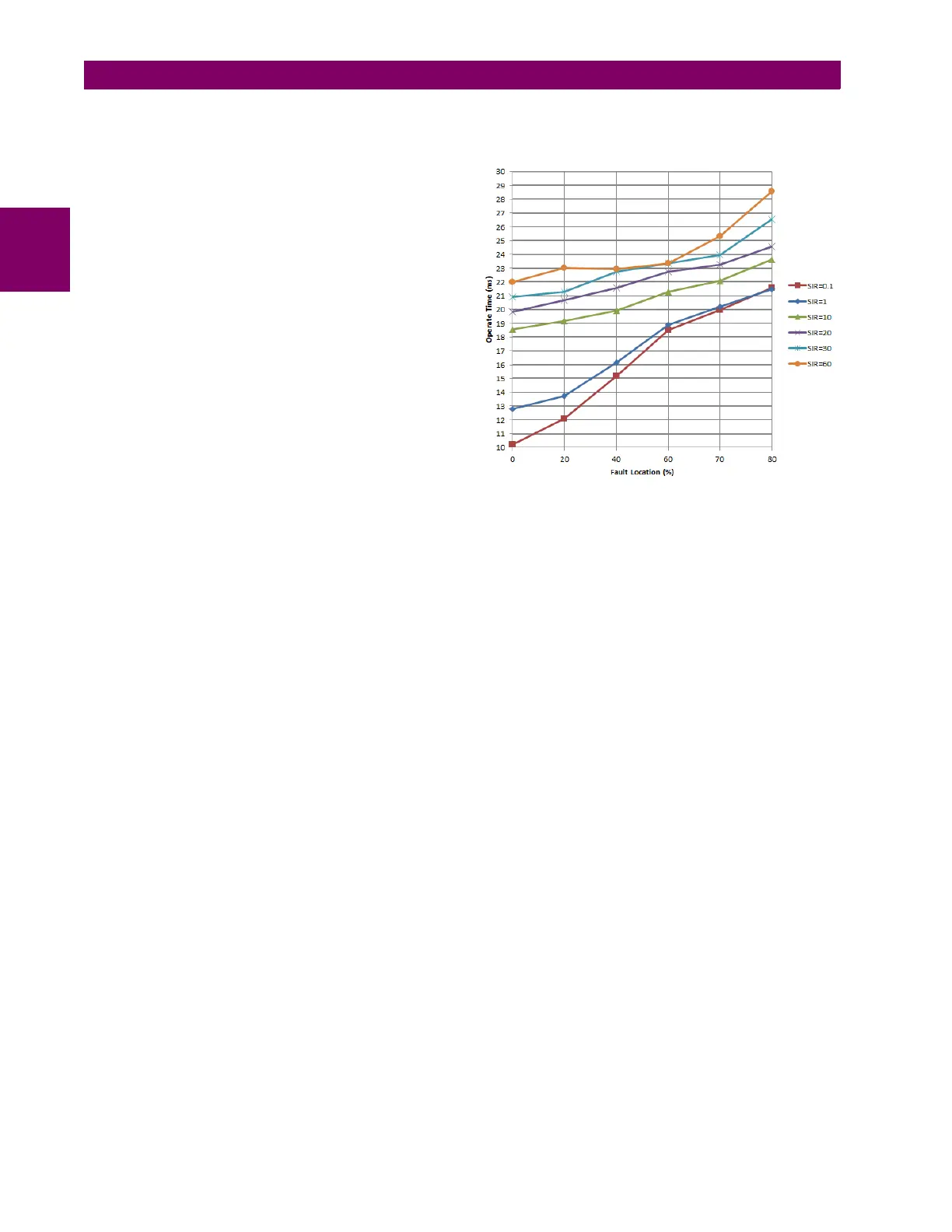
GROUND DISTANCE OPERATING TIME CURVES
The operating times are response times of a microprocessor part
of the relay. See output contacts specifications for estimation of
the total response time for a particular application. The operating
times are average times including variables such as fault inception
angle or type of a voltage source (magnetic VTs and CVTs). The
figure shows ground distance time curves for a 60 Hz system at
nominal system frequency.
LINE PICKUP
Phase instantaneous overcurrent: 0.000 to 30.000 pu
Undervoltage pickup: 0.000 to 3.000 pu
Overvoltage delay: 0.000 to 65.535 s
PHASE/NEUTRAL/GROUND TOC
Current: Phasor or RMS
Pickup level: 0.000 to 30.000 pu in steps of 0.001
Dropout level: 97% to 98% of pickup
Level accuracy:
for 0.1 to 2.0 CT: ±0.5% of reading or ±0.4% of rated
(whichever is greater)
for > 2.0 CT: ±1.5% of reading > 2.0 CT rating
Curve shapes: IEEE Moderately/Very/Extremely
Inverse; IEC (and BS) A/B/C and Short
Inverse; GE IAC Inverse, Short/Very/
Extremely Inverse; I
2
t; FlexCurves™
(programmable); Definite Time (0.01 s
base curve)
Curve multiplier: Time Dial = 0.00 to 600.00 in steps of
0.01
Reset type: Instantaneous/Timed (per IEEE)
Curve timing accuracy
at 1.03 to 20 x pickup: ±3.5% of operate time or ±½ cycle
(whichever is greater) from pickup to
operate
Voltage restraint: modifies pickup current for voltage in the
range of 0.1<V<0.9 VT Nominal in a
fixed linear relationship