GE Multilin D60 Line Distance Protection System 8-3
8 THEORY OF OPERATION 8.1 DISTANCE ELEMENTS
8
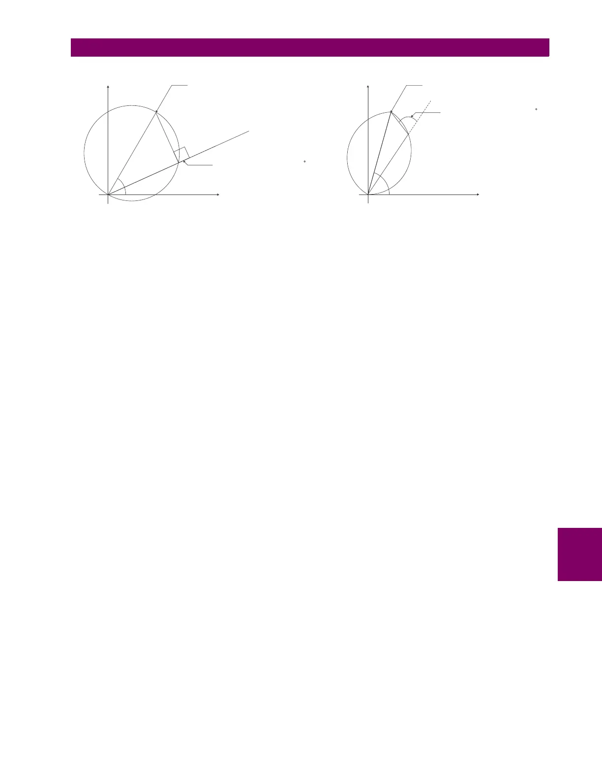
Figure 8–1: MHO AND LENS CHARACTERISTICS
c) NON-DIRECTIONAL MHO CHARACTERISTIC
The non-directional mho characteristic is achieved by checking the angle between:
• AB phase element: (I
A
– I
B
) Z – (V
A
– V
B
) and (V
A
– V
B
)–(I
A
– I
B
) Z
REV
• BC phase element: (I
B
– I
C
) Z – (V
B
– V
C
) and (V
B
– V
C
)–(I
B
– I
C
) Z
REV
• CA phase element: (I
C
– I
A
) Z – (V
C
– V
A
) and (V
C
– V
A
)–(I
C
– I
A
) Z
REV
• A ground element:
I
A
Z + I_0 K0 Z + I
G
K0M Z – V
A
and V
A
– (I
A
Z
REV
+ I_0 K0 Z
REV
+ I
G
K0M Z
REV
)
• B ground element:
I
B
Z + I_0 K0 Z + I
G
K0M Z – V
B
and V
B
– (I
B
Z
REV
+ I_0 K0 Z
REV
+ I
G
K0M Z
REV
)
• C ground element:
I
C
Z + I_0 K0 Z + I
G
K0M Z – V
C
and V
C
– (I
C
Z
REV
+ I_0 K0 Z
REV
+ I
G
K0M Z
REV
)
d) MHO REACTANCE CHARACTERISTIC FOR DIRECTIONAL APPLICATIONS
The reactance characteristic is achieved by checking the angle between:
• AB phase element: (I
A
– I
B
) Z – (V
A
– V
B
) and (I
A
– I
B
) Z.
• BC phase element: (I
B
– I
C
) Z – (V
B
– V
C
) and (I
B
– I
C
) Z.
• CA phase element: (I
C
– I
A
) Z – (V
C
– V
A
) and (I
C
– I
A
) Z.
• A ground element: I
A
Z + I_0 K0 Z + I
G
K0M Z – V
A
and I_0 Z.
• B ground element: I
B
Z + I_0 K0 Z + I
G
K0M Z – V
B
and I_0 Z.
• C ground element: I
C
Z + I_0 K0 Z + I
G
K0M Z – V
C
and I_0 Z.
If the mho characteristic is selected, the limit angle of the comparator is adjustable concurrently with the limit angle of the
mho characteristic, resulting in a tent shape complementing the lens characteristic being effectively applied.
e) QUADRILATERAL REACTANCE CHARACTERISTIC FOR DIRECTIONAL APPLICATIONS
The quadrilateral reactance characteristic is achieved by checking the angle between:
• AB phase element: (I
A
– I
B
) Z – (V
A
– V
B
) and (I
A
– I
B
) Z.
• BC phase element: (I
B
– I
C
) Z – (V
B
– V
C
) and (I
B
– I
C
) Z.
• CA phase element: (I
C
– I
A
) Z – (V
C
– V
A
) and (I
C
– I
A
) Z.
• A ground element: I
A
Z + I_0 K0 Z + I
G
K0M Z – V
A
and (j I_0 or j I_2A) e
j
.
• B ground element: I
B
Z + I_0 K0 Z + I
G
K0M Z – V
B
and (j I_0 or j I_2B) e
j
.
• C ground element: I
C
Z + I_0 K0 Z + I
G
K0M Z – V
C
and (j I_0 or j I_2C) e
j
.
MHO CHARACTERISTIC LENS CHARACTERISTIC
R
Reach setting
X
837715A2.CDR
Comparator angle setting= 90
R
Comparator angle setting < 90
Reach setting
X
837714A2.CDR