OPM_LPS_33E_10K_30K_4CN_V010.doc 33/82 Operating Manual LP 33 / 10-20-30 kVA
4.8.4 RPA system - Control bus connection
WARNING !
This operation must be performed by trained personnel before the initial start-
up (ensure that the UPS installation is completely powered down).
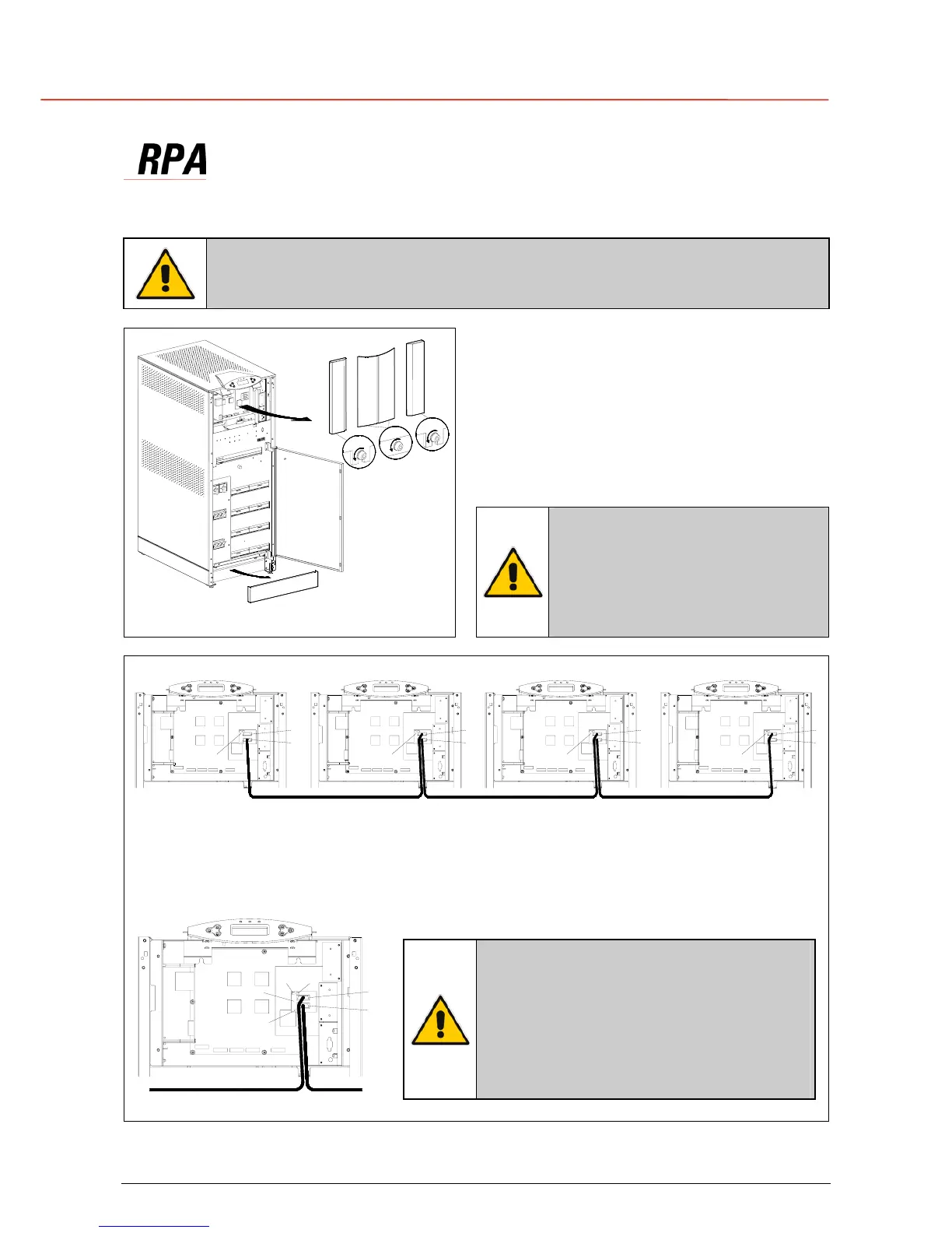
Access to the RPA board
1 - Open the front door “A” of the cabinet.
2 - Remove the protection covers “B, C, D”
fixed with screws “F”.
3 - Remove the front panel protection cover “C”
by pulling it off.
SGT4000_010-020_RPA connection_01
F
A
E
D
B
F
C
F
Fig. 4.8.4-1 Access to the RPA board
NOTE !
When fixing again the protection
covers, make sure that the
screws “F” are as tight as
possible since they serve also as
earth connection.
SGT4000_010-020_RPA connection_02GB
UPS 2
P16
J3
J4
UPS 3
P16
J3
J4
P16
UPS 4
J4
J3
P2 P2 P2 P2
P15 P15 P15 P15
P16
J4
J3
UPS 1
Fig. 4.8.4-2 Bus connection RPA parallel system
Bus connection RPA parallel system
Connect the control bus cable between the parallel units as indicated in the diagram Fig. 4.8.4-2.
Provide that the connectors J3 and J4 are properly fixed with the included screws.
The jumper JP1 - JP2 - JP3 must be
removed only on the intermediate units,
where the connectors J3 and J4 are both
inserted.
Do not insert or remove J3 and J4 from
the board “P16 - Connector adapter RPA”
when the parallel system is operating.
SGT4000_010-020_RPA connection_03
JP2JP1
JP3
P16
J3
J4
Fig. 4.8.4-3 Connection to Board P16

 Loading...


