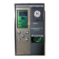
EntelliGuard®TU Trip Unit
Section 1 – General Information 09/25/08
8 © 2008 General Electric All Rights Reserved
Figure 4: Trip Unit Keypad
• UP: Scroll up or increment value
• DOWN: Scroll down or decrement value
• RIGHT: Next function or next page
• LEFT: Previous function or previous page
• ENTER: Save or set in to memory
Electrical Requirements
None: Plug in installation. Done on un-energized units.
Equipment Interfaces
Power Break I, Power Break II, WavePro, AKR and
EntelliGuard G Circuit Breakers.
Trip units, for the most part, do not require direct
connections to the equipment. All wiring is intended to
connect to the circuit breaker or cassette. Connections
that are required for other equipment are the optional
zone-selective interlock, input, and relay output made by
the secondary disconnect, and the neutral sensor, which
uses a special dedicated disconnect.
Zone-selective interlocking coordinates breakers so that
the downstream breaker is allowed the first opportunity
to clear a fault or overload event. The types of available
zone-selective interlocking are Z, which reacts to ground
faults and short time pickups, and T, which reacts to
ground faults, short-time and instantaneous pickups.
Input 1 can be programmed for reduced instantaneous
or trip the breaker. Other inputs can be programmed to
trip the breaker only.
Power Break I, Power Break II, WavePro and AKR Trip
Units have one relay. EntelliGuard G Trip Units have two
output relays. The relay output can be assigned to the
following functions:
• GF Alarm
• Over-current trip (GF, INST, LT, ST)
• Reduced Instantaneous (RELT) Active
• Protective Relays
• Current Alarm 1
• Current Alarm 2
• Health status
The trip units must have the specific option (as an
example protective relay must be enabled in order for
protective function to actuate the relay) enabled in order
to actuate the relay.
In addition to the inputs indicated above, Power Break I,
Power Break II, WavePro, AKR , and EntelliGuard G Trip
Units also receive inputs from external voltage
conditioners, a +24 VDC control power supply, and
communication connections. (Note: external +24 VDC
control power is required for communication.)
All trip unit types have a connection to an auxiliary switch
within the breaker that senses the breaker’s position.
COMMUNICATIONS
External +24 VDC control power is required for
communications.
Power Break I, Power Break II, WavePro, AKR, and
EntelliGuard G Trip Units support Modbus communication
protocol. In addition, EntelliGuard G Trip Units support
Profibus communication.
Modbus and Profibus connections are made directly to
wiring terminations on breaker frames. All
Modbus/Profibus connections are made through the trip
unit’s back (Power Break I, Power Break II, WavePro and
AKR Trip Units) and top (EntelliGuard G Trip Units)
connectors, which mate with a receptacle on the breaker
frame. These additional connections are made to the
equipment through the secondary disconnects of the
breaker.
Modbus
The Trip Units are fully compliant with Modbus Protocol.
Full details of the Modbus protocol can be found in the
Modbus Protocol Specification.
Two wire Modbus 485 are supported.
The link Host may operate at a 300, 600, 1200, 2400,
4800, 9600 or 19200-baud rate.

 Loading...


