INSTALLATION, OPERATIONS AND MAINTENANCE MANUAL 5
This publication provides guidelines for installation
and maintenance of Evolution Motor Control
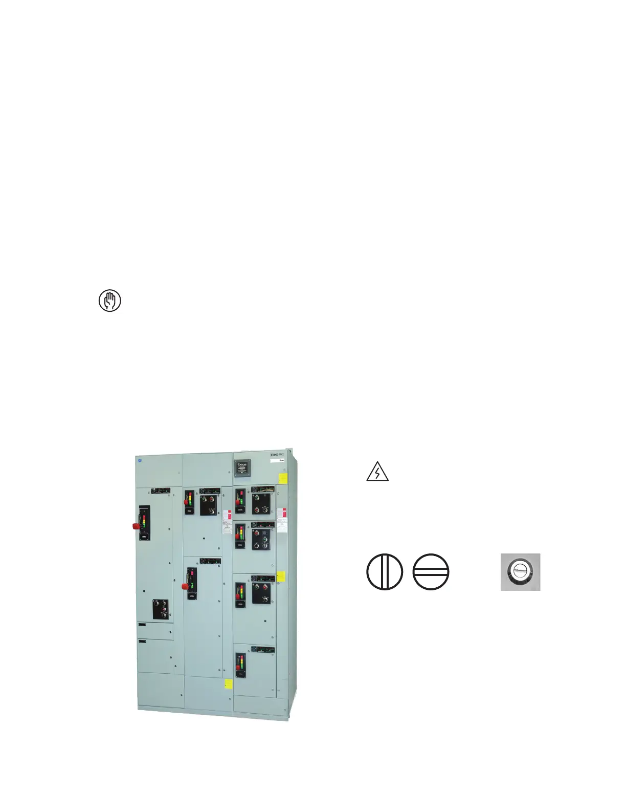
Centers, as shown in Figure 1. The information
provided does not cover all details or variations
in this product offering, nor does it address all
possible contingencies to be met in connection
with installation, operation, or maintenance.
Should further information be desired, contact
Post Sales Support: 1-888-437-3765
Refer to the requisition number found on the front
of the equipment when calling for assistance.
Disconnect equipment from all electrical
services before performing any installation
or maintenance work.
For additional information, including safety
considerations for personnel working on this
product, see NEMA Standard Publication No. ICS
2.3, Instructions on the Handling, Installation,
Operation, and Maintenance of Motor
Control Centers.
General description – vertical section enclosures
Each Evolution MCC vertical section is assembled
with two full-side sheets having openings near the
top and bottom for lateral busing and wiring
between sections. Multiple sections are joined
together at the factory in three-section (maximum)
shipping splits. Each shipping split is provided with
continuous floor sills and a lifting angle. Floor sills
and lifting angles are field removable. Each
shipping split includes a continuous non-removable
main horizontal bus. Main bus splice bars are
provided within each shipping split for field
connecting main busses. Refer to motor control
center outline drawings furnished by ABB for
location of shipping splits within each motor
control center lineup. Hinged doors are provided
over horizontal and vertical wireways. (These doors
can be removed by extracting the hinge pins inside
the doors.)
Vertical sections are normally provided with a
top (12-inch high) horizontal wireway and a bottom
(6-inch high) horizontal wireway. Non-arc resistant
vertical section is provided with a vertical (4-inch
wide) wireway. Each arc-resistant vertical section is
provided with a vertical (3.85-inch wide) wireway.
To open unit doors, rotate the latches 90'
counter-clockwise until the screwdriver
slots or knobs are vertical.
To open wireway doors, rotate the latches
90' clockwise until the screwdriver slots or
knobs are vertical.
Because of the great variety of motor controller
assemblies and components provided within
industrial motor control centers and to satisfy
floor-space limitations at installation sites, a large
variety of vertical section dimensions are provided,
as follows:
• Section Height: 90-inch², 78-inch¹, 66-inch¹ etc.
• Section Width: 20-inch, 24-inch, 30-inch etc.
• Section Depth: 13-inch¹, 20-inch, 22-inch or
deeper for large assemblies.
1. Not available in arc-resistant.
2. Sections with top fans and top vents will add 5" Sections with pull
box and plenum will add 12".
Introduction
—
01
Evolution Series
three-section lineup
—
01
Secure Unit Door Latch shown in secure positionOpen
 Loading...


