INSTALLATION, OPERATIONS AND MAINTENANCE MANUAL 7
Bus splicing
Main, neutral and ground bus splice bars (with all
associated hardware) are furnished, as necessary,
to join sections together. They are located in the
first section to the right of the joint.
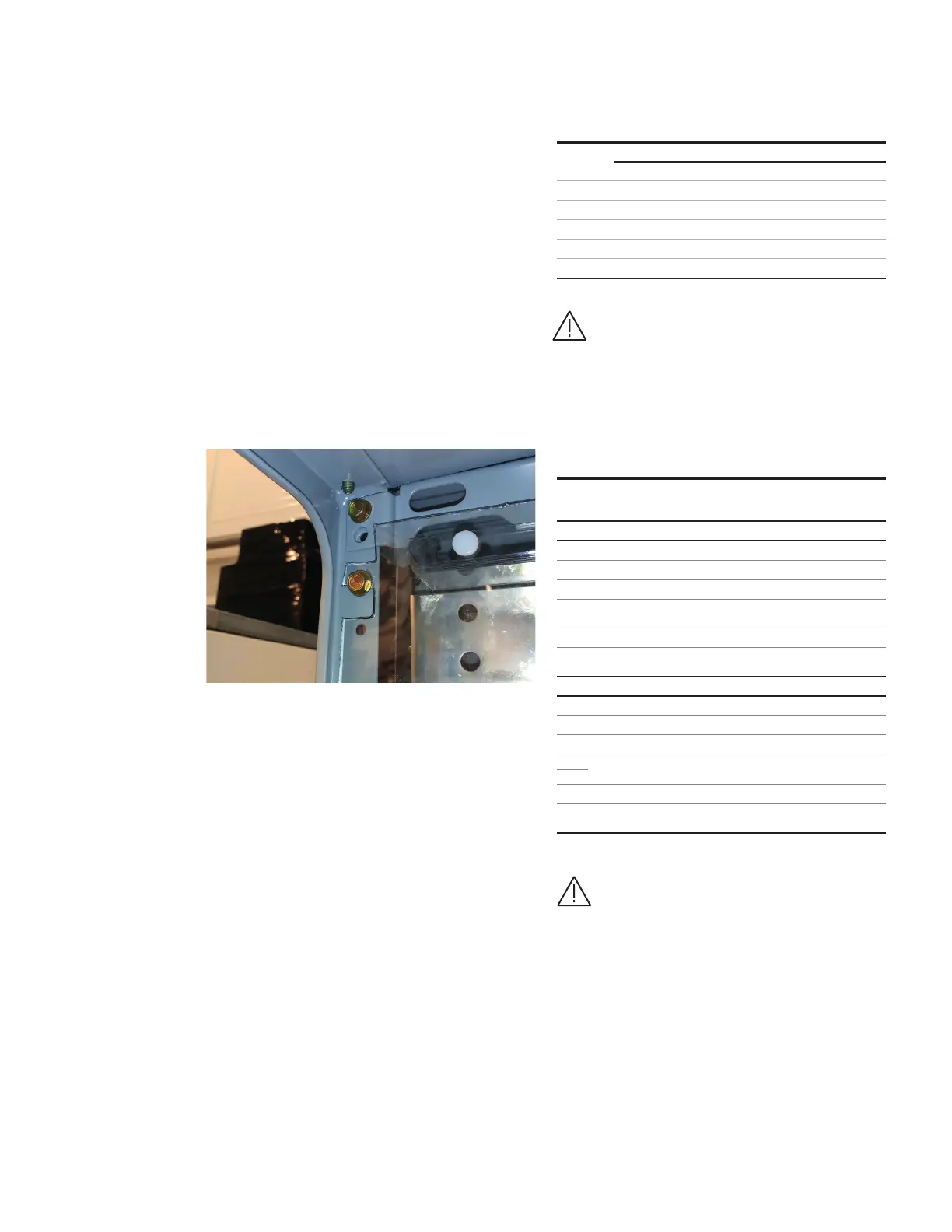
Remove the top Lexan barrier, as shown in Figure
2A and Figure 04, to access the main bus. Refer to
instruction drawings in splice kit. See Table 2.
Arc-resistant design has metallic barrier in addition
to the Lexan barrier which also must be removed to
access the main bus. Arc-resistant shipping splits
will arrive with end caps. When bus splicing, please
remove these end caps to make connection, only
the furthest most left and right end caps shall
remain.
—
04
Horizontal bus barrier
mounting slot and screw
—
04
Amps Main Bus Splice
Assembly Kit
Bars/
Phase
Copper
Size (in.)
(thick x
width)
SC Rating
(sym.amps)
Splice
Instruction
Drawing*
Standard Splicing
Bolt Size
Copper Joints Aluminum Joints
lb-ft N-m lb-ft N-m
Torque values for various bolt sizes and joint types.
Bus splice kits
When assembling or connecting
to aluminum bus, apply a suitable
joint compound between the
contacting surfaces.
*Included in kits
Standard plating is tin. Refer to
factory for alternate plating.