Dishwasher Installation
10
STEP 15: POSITION DISHWASHER, SECURE
TO COUNTERTOP OR CABINET
In this step you will need the 2 Phillips special head screws
from the screws set aside in Step 1.
The dishwasher must be secured to the countertop or the
cabinet sides. When the underside of the countertop is wood,
use Method 1. Use Method 2 when the underside of the
countertop is made of a material, such as granite, that will not
accept wood screws.
IMPORTANT – Prevent door panel and control
panel damage. Dishwasher must be positioned so the front
panel and control panel do not contact the adjacent cabinets
or countertop. Mounting screws must be driven straight and
flush. Protruding screw heads could scratch the door panel or
control panel and interfere with door operation.
Method 1
Secure dishwasher to underside of wood countertop.
5HFKHFNDOLJQPHQWRIWKHGLVKZDVKHULQWKHFDELQHW5HIHUWR
Steps 13 and 14. Door panel and/or control panel must not
hit cabinets or countertop.
)DVWHQWKHGLVKZDVKHUWRWKHXQGHUVLGHRIWKHFRXQWHUWRS
with the 2 Phillips special head screws. Refer to Figure T.
0DNHFHUWDLQVFUHZVDUHGULYHQVWUDLJKWDQGÀXVKWRSUHYHQW
panel damage.
,QVWDOOSOXJEXWWRQVWRWKHVLGHRIWKHWXEZHOOLQWKHKROHV
provided.
Method 2
Secure dishwasher to cabinet sides.
5HFKHFNDOLJQPHQWRIWKHGLVKZDVKHULQWKHFDELQHW5HIHUWR
Steps 13 and 14. Door panel and/or control panel must not
hit cabinets or countertop.
)DVWHQWKHGLVKZDVKHUWRWKHDGMDFHQWFDELQHWVZLWKWKH
Phillips special head screws provided. Refer to Figure U. Make
FHUWDLQVFUHZVDUHGULYHQVWUDLJKWDQGÀXVKWRSUHYHQWSDQHO
damage.
,QVWDOOSOXJEXWWRQVWRWKHVLGHRIWKHWXEZHOOLQWKHKROHV
provided.
Figure U
Figure T
Brackets
Wood Countertop
Granite Countertop
Side Brackets
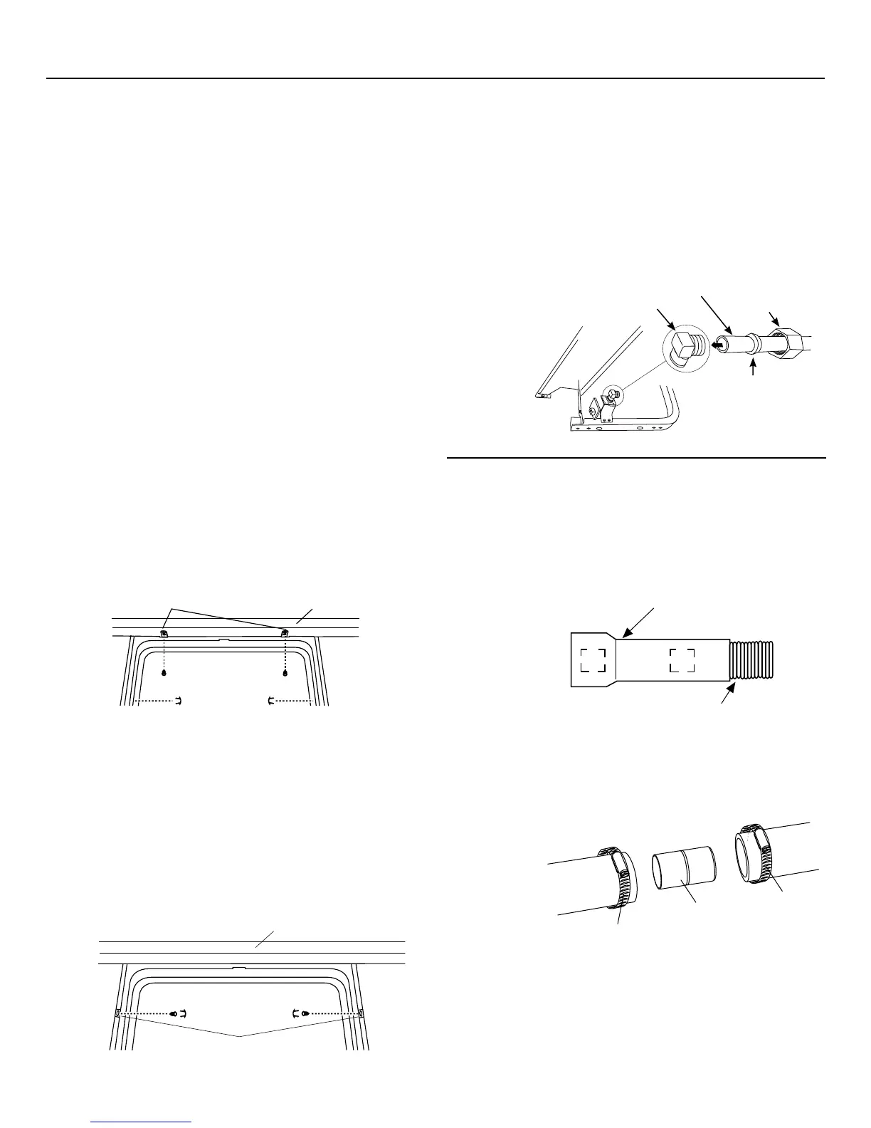
STEP 16: CONNECT WATER SUPPLY
Connect water supply line to 90° elbow.
6OLGHFRPSUHVVLRQQXWWKHQIHUUXOHRYHUHQGRIZDWHUOLQH
,QVHUWZDWHUOLQHLQWRHOERZ
6OLGHIHUUXOHDJDLQVWHOERZDQGVHFXUHZLWKFRPSUHVVLRQQXW
IMPORTANT – Check to be sure that door spring
DQGRUGRRUVSULQJFDEOHGRQRWUXERUFRQWDFWWKH¿OOKRVHRU
water supply line.
Test by opening and
closing the door.
Reroute the water
supply lines if a
rubbing noise or
interference
occurs.
STEP 17: CONNECT DRAIN LINE
The molded end of the drain hose will fit 5/8" through 1"
diameter inlet ports on the air gap, waste tee or disposer.
'HWHUPLQHVL]HRILQOHWSRUW
&XWGUDLQKRVHFRQQHFWRURQWKHPDUNHGOLQHLIUHTXLUHG
WR¿WWKHLQOHWSRUW
,IDORQJHUGUDLQKRVHLVUHTXLUHGDQG\RXGLGQRWSXUFKDVH
drain hose GPF12L, add up to 66" length for a total of 144"
(12 feet) to the factory-installed hose. Use 5/8" or 7/8" inside
diameter hose and a coupler to connect
the 2 hose ends.
Secure the
connection
with hose
clamps.
Figure W
Figure X
NOTE: TOTAL DRAIN HOSE LENGTH MUST NOT EXCEED 12 FEET
FOR PROPER DRAIN OPERATION.
7^bT2[P\_
2^d_[Ta
7^bT2[P\_
Figure V
Cutting Line
1"
5/8"
IMPORTANT: Do not cut corrugated
portion of hose
Compression
Nut
Hot Water
Supply Line
90° Elbow
Ferrule
Bottom Left Side
 Loading...