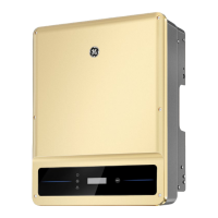
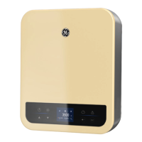
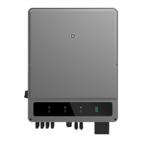
The provided document is a user manual for the GEP series of three-phase PV string grid-tied inverters, ranging from 4 kW to 20 kW. This manual covers product information, installation, electrical connection, commissioning, troubleshooting, and maintenance.
Function Description
The GEP inverter converts DC power generated by PV modules into AC power and feeds it into the utility grid. It is a three-phase PV string grid-tied inverter designed for various application scenarios. The inverter includes multiple communication ports (COM1, COM2, COM3) for connecting communication modules (Bluetooth, WiFi, LAN, 4G), RS485 communication cables, DRED (Demand Response Enabling Device) or remote shutdown communication cables, and for connecting to other inverters or data loggers. It also supports anti-backfeed functionality by connecting to a meter and CT.
Important Technical Specifications
Applicable Models:
- GEP4.0-3-10 (4kW)
- GEP5.0-3-10 (5kW)
- GEP6.0-3-10 (6kW)
- GEP8.0-3-10 (8kW)
- GEP10-3-10 (10kW)
- GEP12-3-10 (12kW)
- GEP15-3-10 (15kW)
- GEP20-3-10 (20kW)
- GEP10-3-AU10 (10kW)
- GEP8-3-AU10 (8kW)
Nominal Output Voltage:
- 3/N/PE, 220/380Vac
- 3/N/PE, 230/400Vac
- 3/N/PE, 240/415Vac
Input (across models):
- Max. Input Power: Ranges from 8,000 W (GEP4.0-3-10) to 40,000 W (GEP20-3-10).
- Max. Input Voltage: 1100 Vd.c. for all models.
- MPPT Operating Voltage Range: 140–950 Vd.c. for all models.
- MPPT Voltage Range at Nominal Power: Varies by model, e.g., 160–850 V (GEP4.0-3-10) to 360–850 V (GEP10-3-10, GEP20-3-10).
- Start-up Voltage: 180 V for all models.
- Nominal Input Voltage: 620 V for all models.
- Max. Input Current per MPPT: 15 A (GEP4.0-3-10 to GEP6.0-3-10), 30 A (GEP8-3-AU10 to GEP20-3-10).
- Max. Short Circuit Current per MPPT: 18.7 A (GEP4.0-3-10 to GEP6.0-3-10), 37.5 A (GEP8-3-AU10 to GEP20-3-10).
- Number of MPP Trackers: 2 for all models.
- Number of Strings per MPPT: 1 (GEP4.0-3-10 to GEP6.0-3-10, GEP10-3-10), 2 (GEP8-3-AU10 to GEP20-3-10).
Output (across models):
- Nominal Output Power: Matches the model's nominal power (e.g., 4,000 W for GEP4.0-3-10, 20,000 W for GEP20-3-10).
- Nominal Output Apparent Power: Matches the model's nominal power.
- Max. AC Active Power: Slightly higher than nominal output power (e.g., 4,400 W for GEP4.0-3-10, 22,000 W for GEP20-3-10).
- Nominal Output Voltage: 380/400/415 V, 3/N/PE.
- Output Voltage Range: 180–260 V.
- Nominal AC Grid Frequency: 50/60 Hz.
- Max. Output Current: Varies by model, e.g., 6.4 A (GEP4.0-3-10) to 32.0 A (GEP20-3-10).
- Power Factor: ~1 (Adjustable from 0.8 leading to 0.8 lagging).
- Max. Total Harmonic Distortion: <3%.
- Maximum Output Overcurrent Protection: Varies by model, e.g., 22.13 A (GEP4.0-3-10) to 88.93 A (GEP12-3-10 to GEP20-3-10).
Efficiency:
- Max. Efficiency: 98.3% (GEP4.0-3-10 to GEP10-3-AU10), 98.4% (GEP12-3-10 to GEP20-3-10).
- European Efficiency: 97.6% (GEP4.0-3-10 to GEP10-3-AU10), 97.8% (GEP12-3-10 to GEP20-3-10).
- CEC Efficiency: 97.8% (GEP4.0-3-10 to GEP10-3-10), 98.0% (GEP10-3-AU10 to GEP20-3-10).
Protection:
- PV Insulation Resistance Detection: Integrated.
- Residual Current Monitoring: Integrated.
- PV Reverse Polarity Protection: Integrated.
- Anti-islanding Protection: Integrated.
- AC Overcurrent Protection: Integrated.
- AC Short Circuit Protection: Integrated.
- AC Overvoltage Protection: Integrated.
- DC Switch: Integrated.
- DC Surge Protection: Type II.
- AC Surge Protection: Type III (Type II Optional).
- AFCI (Arc Fault Circuit Interrupter): Optional.
General Data:
- Operating Temperature Range: -30°C to +60°C.
- Relative Humidity: 0–100%.
- Max. Operating Altitude: 4000 m (3000 m for Australia models).
- Cooling Method: Natural Convection.
- User Interface: LED, LCD (Optional), WLAN+APP.
- Communication: RS485 or WiFi or LAN or 4G (Optional).
- Communication Protocols: Modbus-RTU (SunSpec Compliant).
- Weight: Ranges from 20.5 kg to 26.0 kg depending on the model.
- Dimension (W×H×D): 415×511×175 mm for all models.
- Noise Emission: <25 dB (GEP4.0-3-10 to GEP10-3-AU10), <50 dB (GEP12-3-10 to GEP20-3-10).
- Topology: Non-isolated.
- Self-consumption at Night: <1 W.
- Ingress Protection Rating: IP65.
- Anti-corrosion Class: C4.
- DC Connector: MC4 (2.5–4mm²).
- AC Connector: OT Terminal.
- Environmental Category: 4K4H.
- Pollution Degree: III.
- Overvoltage Category: DC II / AC III.
- Protective Class: I.
- The Decisive Voltage Class (DVC): PV:C AC:C Com:A.
- Active Anti-islanding Method: AFDPF + AQDPF (Active Frequency Drift with Positive Feedback, Active Q Drift with Positive Feedback).
- Country of Manufacture (Only for Australia): China.
Usage Features
The GEP inverter is designed for ease of use and monitoring:
- User Interface: Features an LED indicator for working status, an optional LCD for parameter checking, and buttons for navigation.
- Communication: Supports various communication modules (Bluetooth, WiFi, LAN, 4G) for remote monitoring and parameter setting via the SolarGo App or web pages.
- Parameter Setting: Inverter parameters can be set via the LCD or the SolarGo App, including grid parameters, communication settings, and power limit controls (soft limit and hard limit).
- Monitoring: The Power Sight platform allows for managing organizations/users, adding plants, and monitoring plant status.
- Safety Features: Includes various protection mechanisms such as PV insulation resistance detection, residual current monitoring, PV reverse polarity protection, anti-islanding protection, AC overcurrent/short circuit/overvoltage protection, DC switch, DC/AC surge protection, and optional AFCI.
- Grid Type Support: Supports TN-S, TN-C, TN-C-S, TT, and IT grid types. For grid types with a neutral wire, the N to ground voltage must be less than 10V.
- DRED and Remote Shutdown: Reserved ports for DRED (Australia and New Zealand) and remote shutdown (Europe) in compliance with local grid regulations.
- Shadow MPPT: Features a shadow scan function to optimize power generation when PV panels are shadowed.
- LVRT/HVRT: Low Voltage Ride Through (LVRT) and High Voltage Ride Through (HVRT) functions ensure the inverter remains connected to the utility grid during short-term low or high voltage exceptions.
Maintenance Features
The manual outlines routine maintenance procedures to ensure optimal performance and longevity of the inverter:
- System Clean: Check the heat sink, air intake, and air outlet for foreign matter or dust every 6-12 months.
- Fan Check: Inspect the fan for proper working status, low noise, and intact appearance annually.
- DC Switch Check: Turn the DC switch on and off ten consecutive times annually to ensure proper functionality.
- Electrical Connection Check: Verify that cables are securely connected, not broken, and that no copper core is exposed every 6-12 months.
- Sealing Check: Ensure all terminals and ports are properly sealed. Reseal any cable holes that are not sealed or are too large annually.
- THDi Test: For Australia requirements, a THDi test should be performed as needed, adding Zref between the inverter and mains.
- Troubleshooting Guide: Provides a comprehensive troubleshooting section for common faults like "Ver. Error," "Utility Loss," "Vac Fail," "Fac Fail," "Isolation Fail," "DC inject High," "Ground I Fail," "PV Over Voltage," "Over Temperature," "AFan Fail," "EFan Fail," "IFan Fail," "ARC Fault," and various internal inverter faults. Solutions include software upgrades, checking electrical connections, verifying grid parameters, and inspecting physical components.
- Safety Precautions: Emphasizes disconnecting DC and AC power before any electrical connections, wearing personal protective equipment, and following local laws and regulations.
- Disposal: Instructions for proper disposal of the inverter as electrical equipment waste, not as household waste.