57
Stator Strip Circuit
L1
N
IMC J101-3
IMC J101-2
IMC J1203A - 4
2
1
3
IMC J1203A - 3
IMC J1203A - 2
IMC J1203A - 1
Stator Diagnostics
Stator voltage cannot be tested. If there are any
problems detected with the stator, the inverter will
stop supplying voltage to it. Do the following to test
the stator.
1. Verify the phase wires are properly connected to
the stator.
2. Check stator resistance by disconnecting IMC
J1203A and connect the meter lead between
each phase wire. Resistance should be ~ 16.6 Ω.
Stator Removal
1. Disconnect power to the unit.
2. Remove the rear panel. (See Rear Panel Remov-
al)
3. Remove the 1/2” standard thread rotor nut and
pull the rotor forward.
Note: The rotor is hard to remove because of the
interaction of the rotor magnets with the stator, rock
the rotor back and forth while pulling forward to
remove.
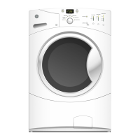
4. Remove the three 1/2” hex stator bolts.
1/2” Hex
1/2” Hex
1/2” Hex
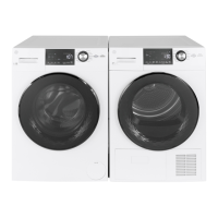
5. Tilt the stator and rest it on the brace as shown
below.
6. Remove the hall sensor. (See Hall Sensor
Removal)
7. Disconnect the three pin wire connector.
Note: When reinstalling this connector, make sure
the connector pins engage properly with the stator
and push the connector until it is fully seated.
 Loading...