Description and operation
General description of the circuit- b reaker
GE Information L12- 039EN/03
2/6
03- 2017
Pole of the circuit- breaker
Description
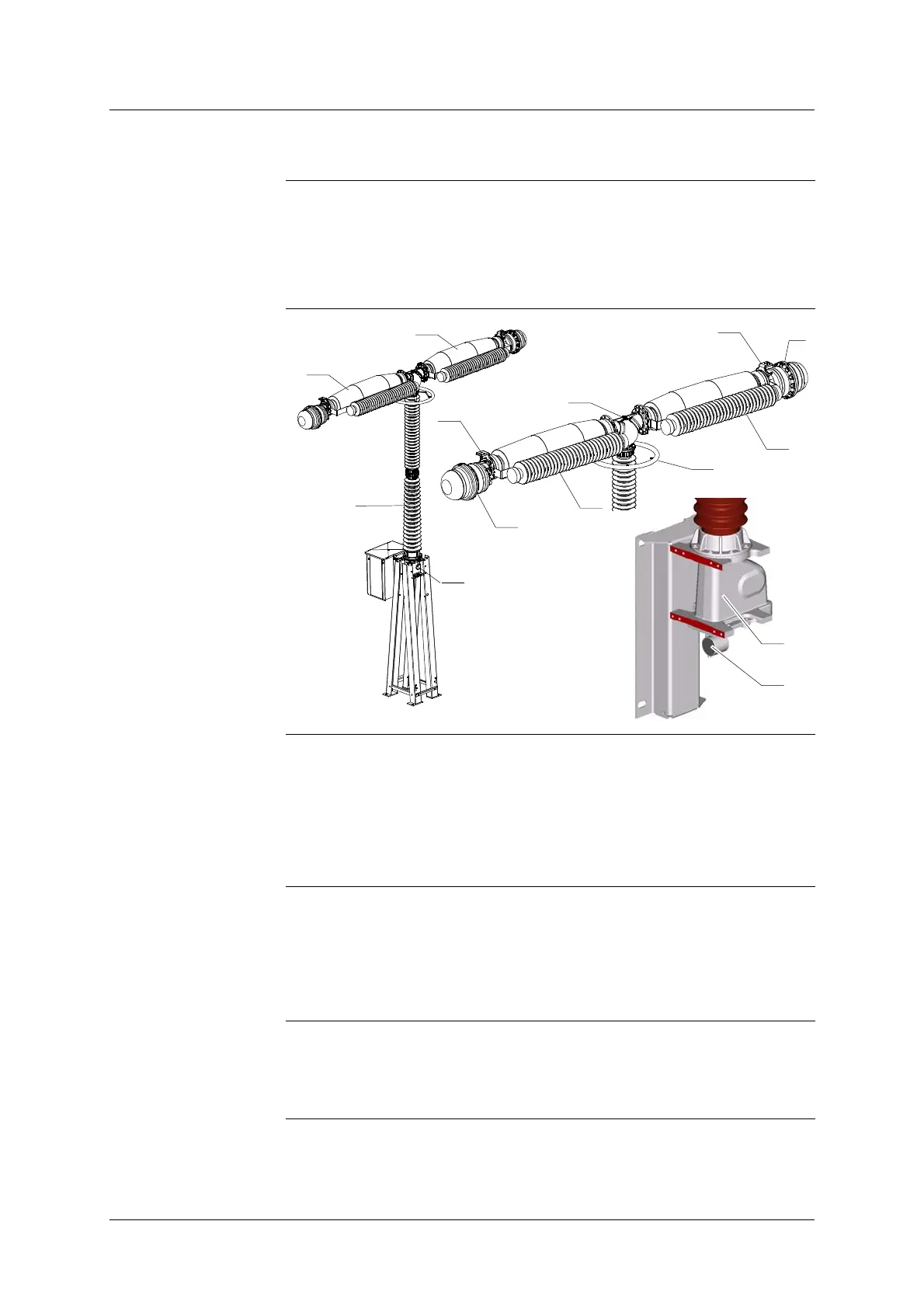
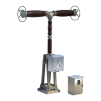
The pole of the circuit- breaker is made up with three main components :
S The interrupting chambers (1).
S The support column (2).
S The housing of the mechanism (3).
Diagram
6
12
1
1
12
5
7
13
3
8
3
5
7
2
Interrupting
chambers
The pole is comprised of two interrupting chambers (1) - in a ceramic envel-
ope - equipped at each end with a resistor (12) and an HV terminal (5).
The interrupting chambers are laid out horizontally and attached, at their
base, to a common housing (6). This housing contains the mechanism used
to transfer the operating movement to the mobile contacts of both chambers.
The interrupting can also be equipped with capacitors (7).
Support column
Consisting of two, three or four ceramic insulators, the support column (2)
allows the circuit- breaker to be ground- insulated and it also encloses the
operating tie- rod which is attached to the interrupting chamber’s moving con-
tacts.
The support column can also be equipped with a corona ring (13).
Housing of the
mechanism
A housing (3) - situated at the base of the column - contains the lever and
crank assembly and which operates the moving contact.
The SF
6
filling and monitoring device (8) is also situated on the housing.




 To Next Page