Description and operation
Description of the interrupting chambers
GE Information L12- 109EN/03
2/4
03- 2017
Interrupting chamber
Quenching medium
The quenching medium is pressurized SF
6
gas or - in particular instances -
pressurized SF
6
+CF
4
gas mixture.
Interrupting principle
The interrupting chamber is of thermal blasting type, using the energy from
the arc, with an auxiliary autopneumatic effect.
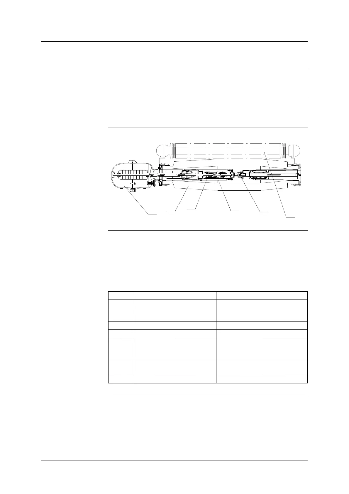
Diagram
3
6
4
2
1
5
Description
The interrupting chamber has been designed in such a way as to increase the
mechanical resistance of the working part and take advantage of the low wear
rate of the contacts subjected to the arc in SF
6
. The working part is enclosed
in a leak tight ceramic envelope, providing insulation between the circuit-
breaker input and output.
The chamber is made up of the following elements :
Mark Component Information
1 Envelope Can have a long creepage dis-
tance, depending on the pollution
level.
2 Fixed contact support Supports the main contacts.
3 Resistor insertion device By- pass the resistor.
4 Moving contact It is worked by the operating mech-
anism and contains the blasting
device.
5 Resistor Used for operation of lines, capa-
citor banks or reactors...
6 Capacitor (depending on the apparatus)