– 39 –
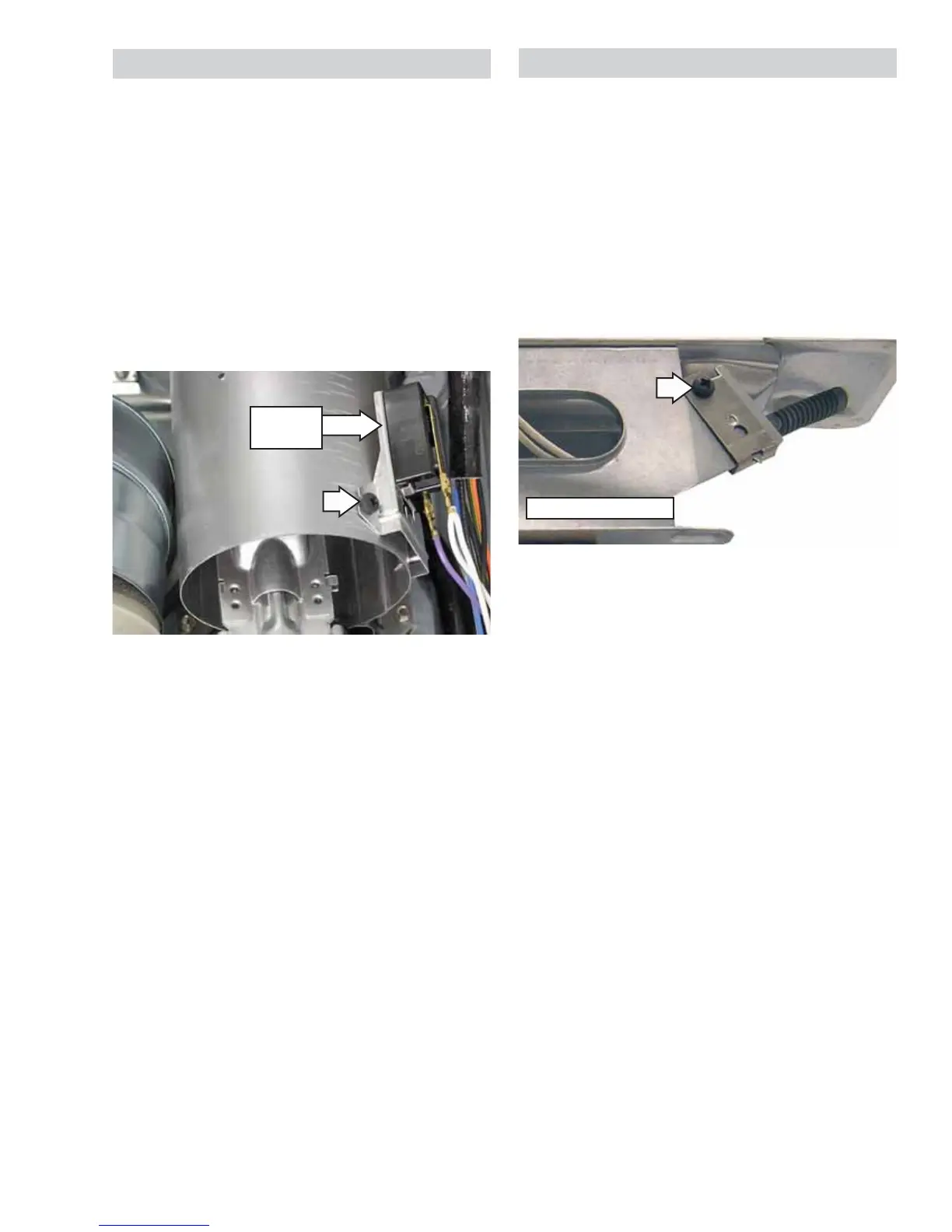
7KHÀDPHGHWHFWRULVDWWDFKHGWRWKHULJKWVLGHRI
the combustion chamber.
Flame Detector Removal
1. Remove the drum. (See Drum in this section
of this service guide.)
2. 'LVFRQQHFWWKHWZRZLUHVIURPWKHÀDPH
detector.
3. Remove the Phillips-head screw that
KROGVWKHÀDPHGHWHFWRUWRWKHFRPEXVWLRQ
chamber.
4. 5HPRYHWKHÀDPHGHWHFWRUIURPWKHWDEDWWKH
bottom.
NOTE: Upon reassembly, ensure the tab at the
ERWWRPRIWKHÀDPHGHWHFWRULVLQVHUWHGLQWRWKH
slot located on the combustion chamber.
The ignitor is located at the end of the burner
assembly in the combustion chamber opening
and has a maximum rating of 4 amps. The ignitor
has an approximate resistance value of 40 to 400
ȍ
The ignitor is attached to the gas valve bracket
with a Phillips-head screw. To access the ignitor,
it is necessary to remove the burner assembly.
(See Gas Valve in this section of this service
guide, steps 1 through 10.)
Gas Valve Bracket
Flame
Detector
Flame Detector
,JQLWRU
 Loading...