Technical specifications
Installation
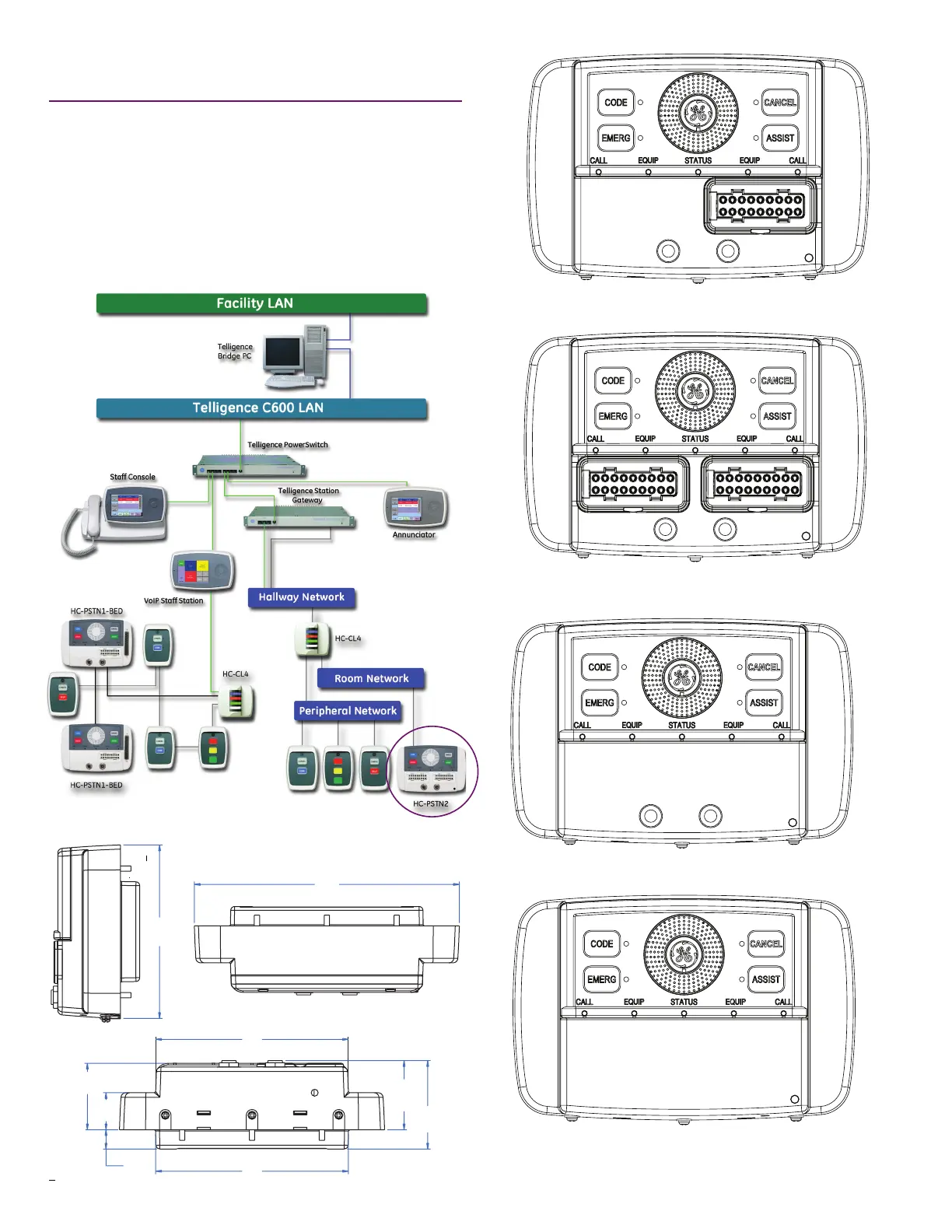
Smart Patient and Staff/Duty Stations connect to the Telligence
LAN/WAN through the Telligence Station Gateway, which
provides all necessary power to the device. Stations are
connected to the gateway via their associated dome light.
Snap-in RJ-45 connections terminate at the station and the
dome light. Stations are network addressable and there are no
DIP switches or jumpers to set. They mount to standard 3-gang
backboxes.
Single Smart Patient Stations (HC-PSTN1) provide one set of connections.
Dual Smart Patient Stations (HC-PSTN2) provide two sets of connections.
Smart Staff/Duty Stations (HC-DUTY) have no bed connections or call cord jacks.
4.5"
(114 mm)
0.5"
(13 mm)
5.0"
(127 mm)
5.0"
(127 mm)
1.8"
(46 mm)
2.3"
(58 mm)
1.7"
(43 mm)
1.0"
(25 mm)
6.9"
(175 mm)
0.5"
(13 mm)
5.0"
(127 mm)
5.0"
(127 mm)
1.8"
(46 mm)
2.3"
(58 mm)
1.7"
(43 mm)
1.0"
(25 mm)
4.5"
(114 mm)
0.5"
(13 mm)
5.0"
(127 mm)
5.0"
(127 mm)
1.8"
(46 mm)
2.3"
(58 mm)
1.7"
(43 mm)
1.0"
(25 mm)
6.9"
(175 mm)
85100-0104; DOC0636754 Rev. 4 (page 2 of 4)
Call Cord Smart Patient Stations (HC-CCPSTN) provide two 0.64 mm (0.25 in)
connectors.