52
INSTALLATION INSTRUCTIONS
(continued)
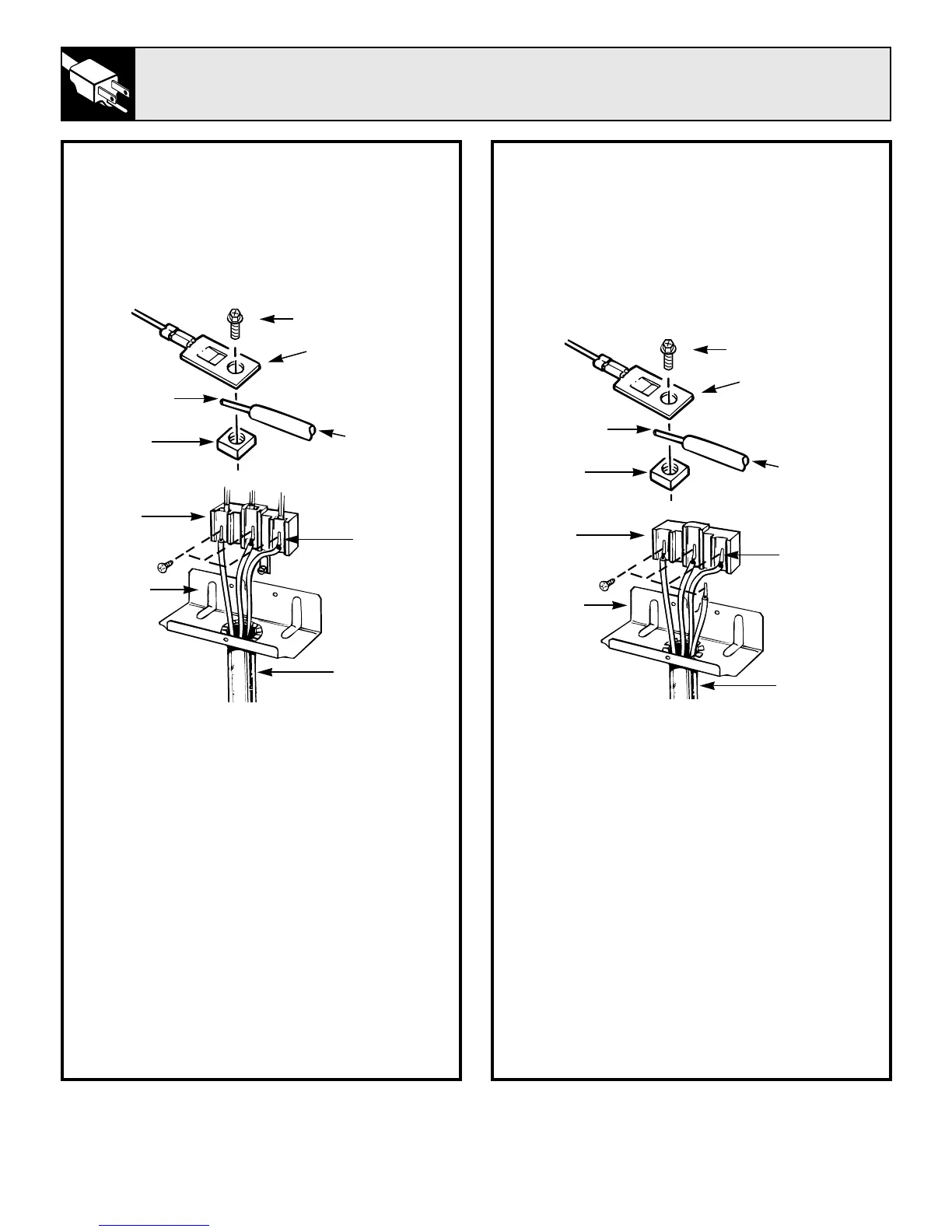
STEP 6
3 WIRE CONDUIT INSTALLATION
Remove the 3 screws from the connector
block. Insert bare wires between the connector
block terminals and movable nuts. Tighten
screws securely. Do not remove ground
strap connection.
WARNING: CONNECTOR BLOCK IS
APPROVED FOR COPPER WIRE
CONNECTION ONLY. IF ALUMINUM
WIRE IS USED, SEE NOTE BELOW.
NOTE: ALUMINUM WIRING
A. Do not connect Aluminum wire to connector
block. Use copper building wire rated for the
correct amperage and voltage to make 3 (three)
3 inch copper jumper wires. Connect wire as per
Step 6 or 7 depending on number of wires.
B. Splice copper wires to aluminum wiring using
special connector terminals designed and UL
approved for joining copper to aluminum and
follow the connector manufacturer’s
recommended procedure closely.
Wire used, location and enclosure of splices,
etc., must conform to good wiring practices and
local codes.
STEP 7
4 WIRE CONDUIT INSTALLATION
Remove the 3 screws from the connector block.
Remove the grounding strap from the connector
block middle location and the screw connecting
it to the frame of the range. Insert bare wires
between the connector block terminals and
movable nuts. Tighten screws securely. Attach
ground wire to the frame of the range.
WARNING: CONNECTOR BLOCK IS
APPROVED FOR COPPER WIRE
CONNECTION ONLY. IF ALUMINUM
WIRE IS USED, SEE NOTE BELOW.
NOTE: ALUMINUM WIRING
A. Do not connect Aluminum wire to connector
block. Use copper building wire rated for the
correct amperage and voltage to make 3 (three)
3 inch copper jumper wires. Connect wire as per
Step 6 or 7 depending on number of wires.
B. Splice copper wires to aluminum wiring using
special connector terminals designed and UL
approved for joining copper to aluminum and
follow the connector manufacturer’s
recommended procedure closely.
Wire used, location and enclosure of splices,
etc., must conform to good wiring practices and
local codes.
BARE
WIRE TIPS
BARE
WIRE TIPS
CONNECTOR
BLOCK
BRACKET
CONDUIT
SCREW
CONNECTOR
BLOCK
TERMINAL
BARE
WIRE
MOVABLE
NUT
FLEXIBLE
CABLE
SCREW
CONNECTOR
BLOCK
TERMINAL
BARE
WIRE
MOVABLE
NUT
FLEXIBLE
CABLE
CONNECTOR
BLOCK
BRACKET
CONDUIT