– 20 –
GEA00840
Igniter Switch
Igniter Switch
2. Lift the igniter switches off the valve stems.
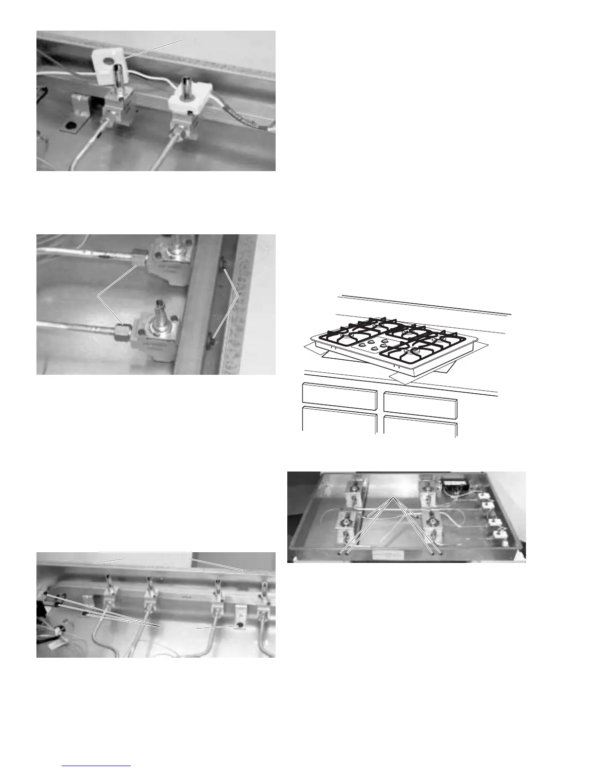
GEA00842
1/2-in.
Screws
1/2-in.
Screws
1/4-in.
Screws
1/4-in.
Screws
3. Remove the 1/2-in. nuts (4) on the gas lines to
the valves and remove the gas lines.
4. Remove the gas fitting located under the
counter from the manifold.
Note: If no work space is available under the
counter, remove 2 hold-down brackets from under
the countertop, lift the burner box from the counter,
turn it 10 degrees, and insert cardboard or wood
under the burner box to protect the countertop.
GEA00782
1/4-in. Screws
1/4-in. Screws
1/4-in.
Screws
1/4-in.
Screws
5. Remove the 1/4-in. screws (2) from the right
side exterior of the burner box.
6. Remove the 1/4-in. screws (4) from the mani-
fold and remove the manifold from the burner
box.
7. Remove the 1/4-in. screws (4) from the mani-
fold and remove the valves.
Brace Removal
1. Remove the burners and top (see Burner and
Top Removal).
2. Remove the burner brackets (see Burner
Bracket Removal).
3. Remove 2 hold-down brackets from under the
countertop, lift the burner box from the counter,
turn it 10 degrees, and insert cardboard or
wood under the burner box to protect the
countertop.
GEA00784
GEA00783
Screws
Screws
4. Remove all brace screws from the exterior of
the burner box.
5. Remove all screws from the braces and
remove the braces.
 Loading...


