EasyManua.ls Logo

GE JKS10 - Oven Component Access Chart

GE JKS10
66 pages
Print Icon
To Next Page IconTo Next Page
To Previous Page IconTo Previous Page
Loading...
– 28 –
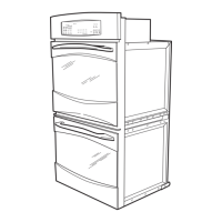
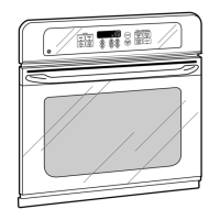
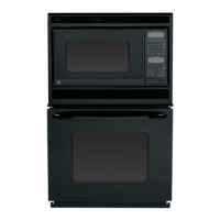
Oven Component Access Chart
WARNING:
The single and double wall ovens are heavy and require two people to remove them from the installation. •
Care should be taken when removing and installing.
Sharp edges may be exposed when servicing. Use caution to avoid injury. Wear Kevlar gloves or •
equivalent protection.
Auxiliary Control Board
zz z
Bake Element
zzzz z
Broil Element
zzzzz
Convection Bake Element
zz z
Convection Fan Blade
zz z
Convection Fan Capacitor
zz z
Convection Fan Motor
zz z
Control Panel Assembly
zz
n/a
zz
Cooling Fan
zz z
Cooling Fan
zz z
Door Assembly
zzzzz
Door Hinge Receiver
zzzz z
Electronic Oven Control
zzzzz
FAD (2 each oven)
zzzzz
Lock Assembly
zzzzz
Meat Probe Outlet
zzzzz
Oven Light Assembly
zzzzz
Oven Temperature Sensor
zzzz z
Thermal Line Break (TCO)
zzzz z
Thermal Switches
zzzzz
Vent Tube/Smoke Eliminator
zzzzz
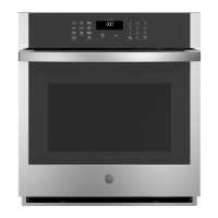
Single
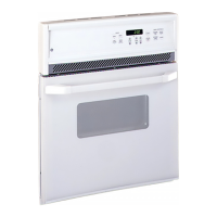
Double Upper
Double Lower
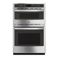
Micromod
Front Serviceable
Oven Components
Components Requiring
Oven Removal