– 26 –
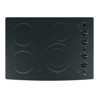
6. Remove the tabs and install them on the new
surface element in the same numbered position.
Note: When installing the new surface element,
make sure a spring is beneath every mounting
bracket.
7. Place the new surface element on the mounting
posts.
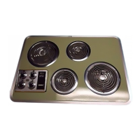
8. Position the sensor harness in the same manner
as the original harness was oriented, being sure
to keep all wires away from all surface elements.
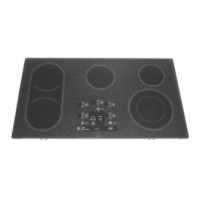
4. Remove the electrical connectors form the
heater.
5. Lift the heater off the springs and mark the
numbers on the bottom of the heater next to the
tabs.
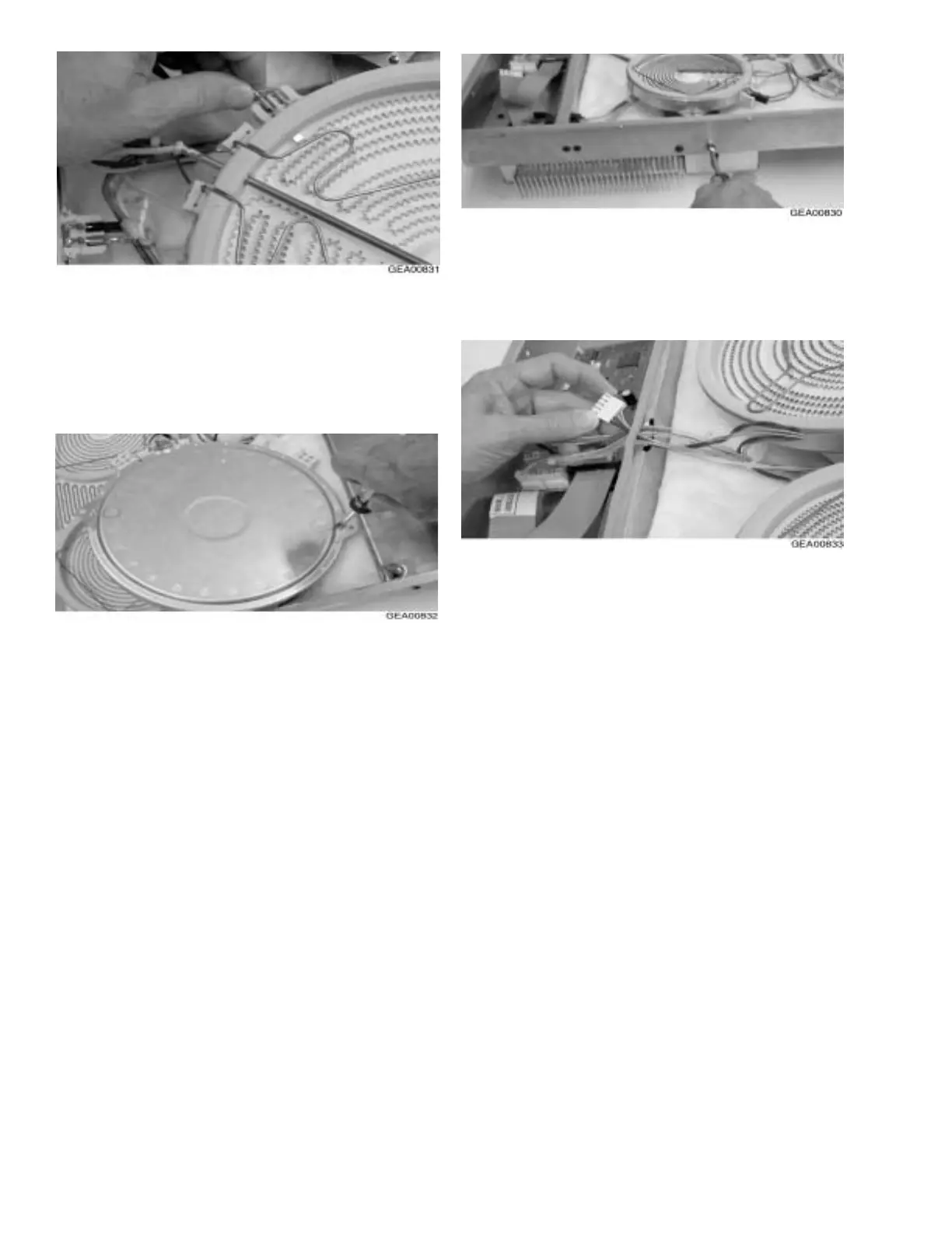
9. Using a nut driver, remove the necessary
screws from the outside of the burner box and
lift the surface element support bracket to
route the sensor wires beneath the bracket.
10. Run the connector through the gap between
the insulating strip and the thermal wall,
making a slit in the insulating strip if neces-
sary.
11. Place the connector on the appropriate header
on the logic board.
12. Beginning at the end of the wire harness
closest to the surface element, secure the
sensor wires to the existing wire harness with
wire ties. Trim the excess material from the
wire ties and make sure the new wire harness
is in the same position as the original.