EasyManuals Logo

GE LOGIQ P5 Technical Publication

GE LOGIQ P5
127 pages
To Next Page IconTo Next Page
To Previous Page IconTo Previous Page
Page #121 background imageLoading...
Page #121 background image
Electrical safety tests
Ultrasound SystemCommon Service Information 4-43
Direction 5444964-100 English Rev. 5
Mains on applied part (continued)
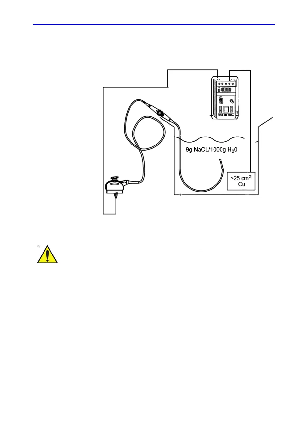
A typical test setup for TEE probes could be as indicated below:
Figure 4-6. TEE probe leakage isolation (sink) current test
NOTE: Where applicable, a typical test setup of non-TEE Probes can
be as illustrated in: Figure 4-4 on page 4-36.
The test passes when the reading measure less than the values
in:
• Table 4-8 on page 4-21.
WARNING
The handle of the TEE probes must not
be immersed.
For immersion levels, please refer to the User Manual.

Table of Contents

Other manuals for GE LOGIQ P5

Questions and Answers:

Question and Answer IconNeed help?

Do you have a question about the GE LOGIQ P5 and is the answer not in the manual?

GE LOGIQ P5 Specifications

General IconGeneral
Power Supply100-240VAC, 50/60Hz
Display15" LCD
Doppler ModesColor Doppler, Power Doppler
Imaging ModesB-Mode, M-Mode
ProbesConvex, Linear, Phased Array
ApplicationsAbdominal, Vascular, Cardiac, OB/GYN, Small Parts, Musculoskeletal
ConnectivityDICOM, USB, Ethernet
Probe Connectors3
PortabilityMobile
Operating Temperature10°C to 40°C
Relative Humidity30%

Related product manuals