SYSTEM PERFORMANCE 7
Rev C
System Pressure Drop
Estimating system pressure drop is the second step in determining net
driving pressure. Pressure drops are created by:
• Tubing friction losses
• Obstructions
• Elevation differences
•Post Filter
•Faucet
• Osmonic pressure
Pressure Drop Through Tubing
The Merlin system uses polyethylene tubing to carry the permeate water.
All tubing creates a pressure drop when water passes through it. This
pressure drop is created by friction within the flowing fluid and is a
function of the flow rate through the tubing and the tubing length. To
simplify this explanation, changes in water density because of
temperature, which does affect tubing pressure drop, have been ignored.
The farther the permeate travels through the tubing, the greater the
pressure drop.
To estimate pressure drop through tubing follow the steps below:
1. Estimate flow rate into the tubing using Table 1.
Use inlet pressure into the Merlin as the Net Driving Pressure for
the purposes of this estimation. By using inlet pressure as the Net
Driving Pressure in Table 1, flow directly from the Merlin without
any pressure drop is found.
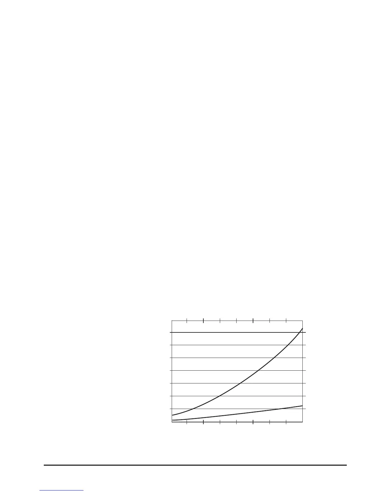
2. Using the estimated flow rate found in step 1 above, find the pressure
drop through the tubing with Figure 4.
Figure 4
0.2 0.3 0.4 0.5 0.6 0.7 0.8 0.9 1.0
0.40
0.35
0.30
0.25
0.20
0.15
0.10
0.05
0
Inlet Flow Rate
m
Pressure Drop / ft. Tubing (psi)
1/2" Tubing
3/8" Tubing
.027
.024
.020
.017
.013
.010
.006
.003
0
.75 1.13 1.51 1.89 2.29 2.65 3.03 3.41 3.78
Inlet Flow Rate (Lpm)
Pressure Drop / .304 m Tubing (bar)
Estimated Tubing Pressure Drop For Water Between 40 - 100˚F (4.4-37.8˚C)