The directional criteria with negative sequence polarisation is given below:
● Directional for
ward: -90° < (angle(I2) - angle(V2 + 180°) - RCA) < 90°
● Directional reverse : -90° > (angle(I2) - angle(V2 + 180°) - RCA) > 90°
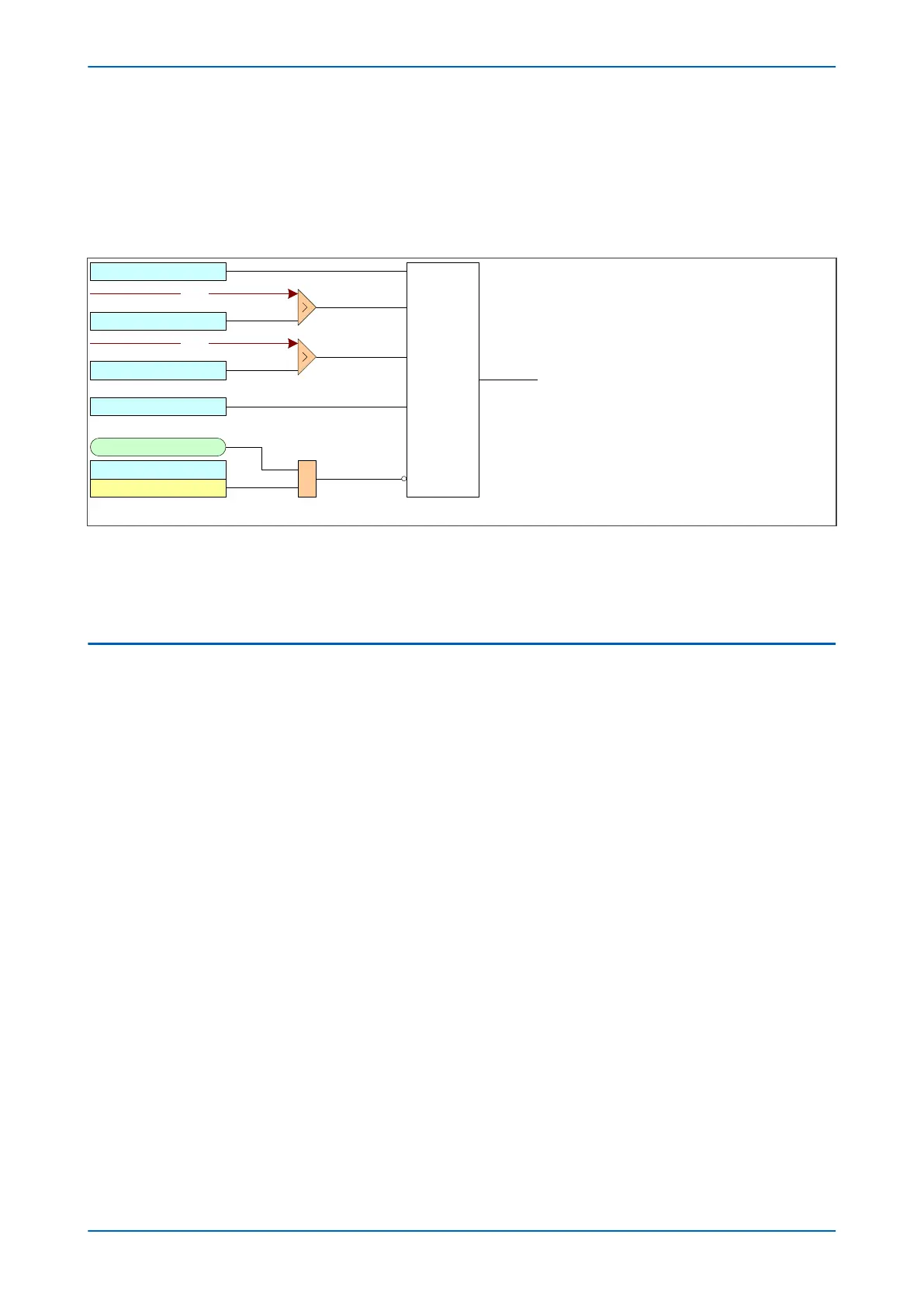
10.4.2.1 DIRECTIONAL EARTH FAULT LOGIC WITH NPS POLARISATION
V00613
VTS Slow Block
IN1> Blocking
VTS Blocks IN>1
IN1> V2pol Set
Directional
check
IN1 > DIRECTIONAL
&
To EF logic
IN1> I2pol Set
Note: This diagram shows the logic for IN 1 (measured earth fault ). The logic for
IN2 (derived earth fault) follows similar principles.
This diagram does not show all stages . Other stages follow similar principles.
IN1> Char Angle
V2
I2
Figure 51: Directional Earth Fault logic with negative sequence polarisation (single stage)
Voltage Transformer S
upervision (VTS) selectively blocks the directional protection or causes it to revert to non-
directional operation. When selected to block the directional protection, VTS blocking is applied to the directional
checking which effectively blocks the Start outputs as well.
10.5 APPLICATION NOTES
10.5.1 SETTING GUIDELINES (DIRECTIONAL ELEMENT)
With directional earth faults, the residual current under fault conditions lies at an angle lagging the polarising
v
oltage. Hence, negativ
e RCA settings are required for DEF applications. This is set in the cell I> Char Angle in the
relevant earth fault menu.
We recommend the following RCA settings:
● Resistance earthed systems: 0°
● Distribution systems (solidly earthed): -45°
● Transmission systems (solidly earthed): -60°
10.5.2 PETERSON COIL EARTHED SYSTEMS
A Petersen Coil earthing system is used in compensated earthing systems, as well as being used in cases of high
impedance ear
thing. P
etersen Coil earthed systems (also called compensated or resonant systems) are commonly
found in areas where the system consists mainly of rural overhead lines. They are particularly beneficial in
locations which are subject to a high incidence of transient faults. In a Petersen Coil earthed system, the network is
earthed via a reactor, whose reactance is tuned to be nominally equal to the total system capacitance to earth.
Similar to insulated systems, if a single-phase to earth fault is applied to a Petersen Coil earthed system, under
steady state conditions no earth fault current flows. The effectiveness of the method in reducing the current to
zero is dependent on the accuracy of the tuning of the reactance value and any changes in system capacitance
(for example due to system configuration changes) require changes to the coil reactance. In practice, perfect
matching of the coil reactance to the system capacitance is difficult to achieve, so that a small earth fault current
will flow.
In isolated and compensated earthed systems, if an earth fault current is below a certain level, then the fault will
self-extinguish due to the low current magnitude. It therefore appears as a transient phenomenon. The figure
Chapter 6 - Current Protection Functions P14x
124 P14xEd1-TM-EN-1
 Loading...


