MicroVersaTrip Plus™ and MicroVersaTrip PM™ Trip Units
Chapter 2. Setup Mode
20
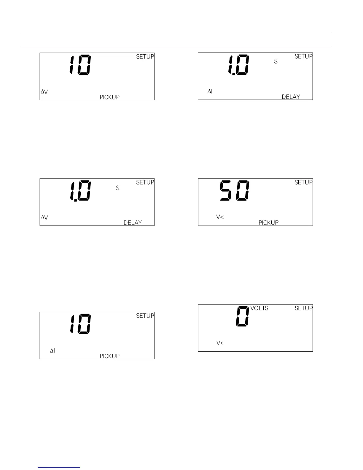
Figure 26. Trip Unit display for voltage-unbalance relay pickup.
Voltage-Unbalance Relay Delay
This function sets the delay time before a voltage-
unbalance trip occurs. The range of delays is 1 to 15
seconds, in steps of 1 second. Choosing
OFF disables
voltage-unbalance protection. The Trip Unit display
is shown in Figure 27.
Figure 27. Trip Unit display for voltage-unbalance relay delay.
Current-Unbalance Relay Pickup
This function compares the true RMS current in the
highest or lowest phase with the average of all three
phases and initiates a trip if the difference exceeds
the set point. The range of set points is 10 to 50% of
the unbalance, with an increment of 1%. The Trip
Unit display is shown in Figure 28.
Figure 28. Trip Unit display for current-unbalance relay pickup.
Current-Unbalance Relay Delay
This function sets the delay time before a current-
unbalance trip occurs. The range of delays is 1 to 15
seconds, in steps of 1 second. Choosing
OFF disables
current-unbalance protection. The Trip Unit display
is shown in Figure 29.
Figure 29. Trip Unit display for current-unbalance relay delay.
Undervoltage Relay Pickup
This function measures the true rms voltage in all
phases and initiates a trip if any phase voltage drops
below the set point. The range of set points is 50 to
90% of the nominal voltage, with an increment of
1%. The Trip Unit display is shown in Figure 30.
Figure 30. Trip Unit display for undervoltage relay pickup.
Undervoltage Relay Zero-Volt Trip Enable
This function determines if the relay trips when all
three phase voltages drop to zero volts. The Trip
Unit display for zero-volt trip disabled is shown in
Figure 31. The Trip Unit display for zero-volt trip
enabled is shown in Figure 32.
Figure 31. Trip Unit display for undervoltage relay zero-volt trip
disabled.