MicroVersaTrip Plus™ and MicroVersaTrip PM™ Trip Units
Chapter 2. Setup Mode
19
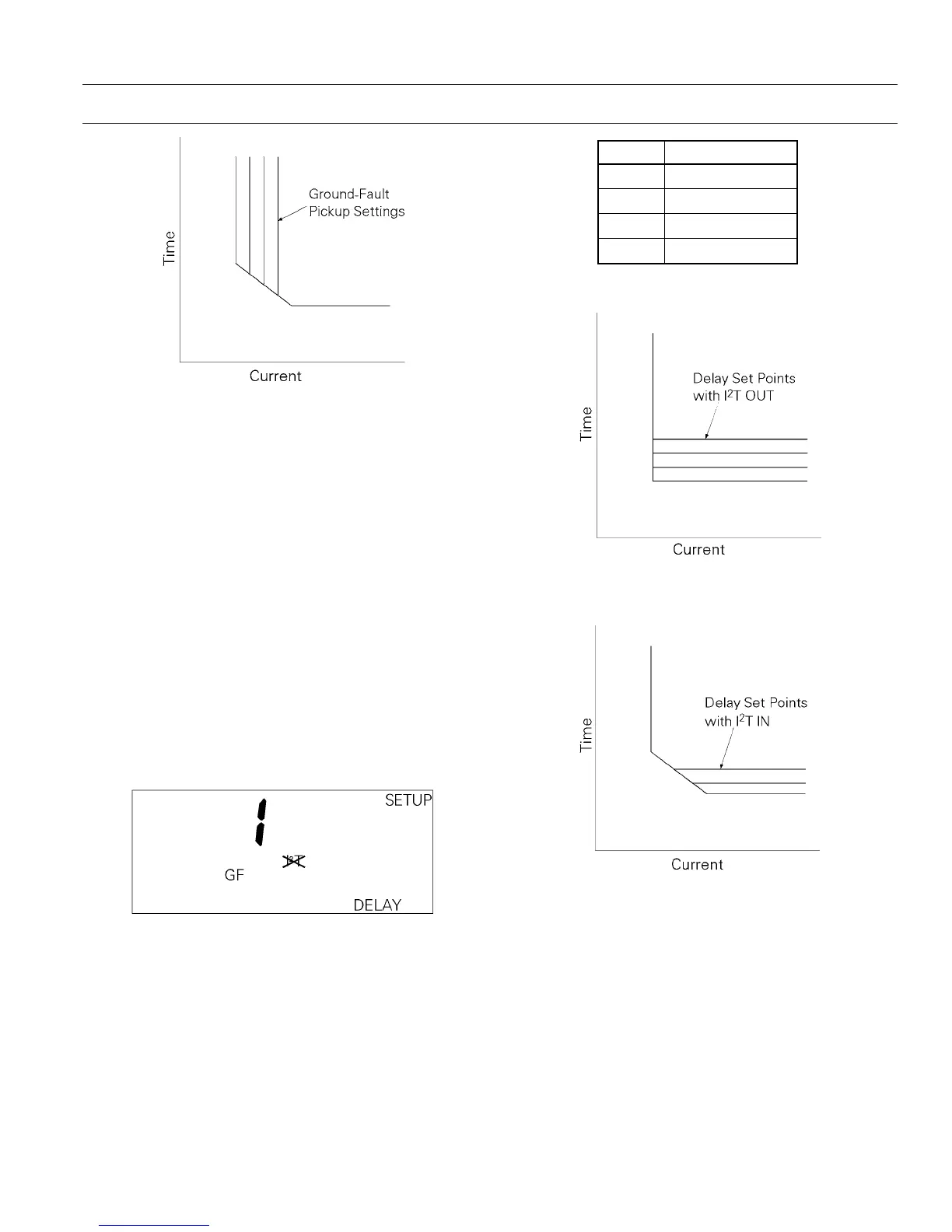
Figure 22. Time-current curve for ground-fault pickup.
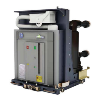
Ground-Fault Delay
This function sets the delay before the breaker trips
when the ground-fault pickup current has been
detected. The Trip Unit display is shown in Figure
23. The choices are listed in Table 15. The delay for
I
2
T OUT is at the lower limit of each band. The delay
for
I
2
T IN is at 200% of the pickup setting at the lower
limit of the band.
The
I
2
T OUT function establishes a constant time
delay, as shown in Figure 24.
I
2
T IN biases the delay
with a constant slope, as shown in Figure 25.
With the X or GD options (switchable ground fault),
an
OFF selection appears as an additional time-delay
set point. Selecting
OFF disables ground-fault protec-
tion.
Figure 23. Trip Unit display for ground-fault delay, showing I
2
T
out.
BB
BB
aa
aa
nn
nn
dd
dd
TT
TT
ii
ii
mm
mm
ee
ee
DD
DD
ee
ee
ll
ll
aa
aa
yy
yy
,,
,,
ss
ss
ee
ee
cc
cc
OFF Disabled
1 0.10
2 0.21
3 0.35
Table 15. Lower-limit delays for ground-fault delay bands.
Figure 24. Time-current curve for ground-fault delay with I
2
T
OUT
.
Figure 25. Time-current curve for ground-fault delay with I
2
T IN.
Voltage-Unbalance Relay Pickup
This function compares the highest or lowest phase
voltage with the average of all three phases and
initiates a trip if the difference exceeds the set point.
The true rms voltage is computed for each phase.
The range of set points is from 10 to 50% of the
unbalance, with an increment of 1%. The Trip Unit
display is shown in Figure 26.