Models PT
Models PT
G5-1-110 & PT
G5-1-110 & PT
G5-2-110
G5-2-110
• Primary terminals that are unfused are 1/4-20 brass screws with one flatwasher
and lockwasher.
• Primary terminals that are fused are 1/4-20 brass screws with one flatwasher
and lockwasher and two nuts.
• Secondary terminals are No. 10-32 brass screws with one flatwasher and
lockwasher.
• The core and coil assembly is vacuum encapsulated in polyurethane resin.
• Thermal burden rating is for 120 volt secondaries.
• Switch gear style is similar to fused style. No fuse or fuse clip is provide, but
inserts for fuse clips are supplied.
• A test card is provided with each unit.
FUSE FOR MODEL
PTG5 TRANSFORMER
RATING
VOLTS
INTERRUPTING
AMPERES (SYM)
SUGGESTED
RATING
CONTINUOUS
AMPERES
CAP DIA.
INCHES
LENGTH
INCHES
CLIP CENTERS
INCHES
7200:120V 15.5kV 80,000 1.0E 1.63 13 11.50
4800:120V 15.5kV 80,000 1.0E 1.63 13 11.50
11000:120V 15.5kV 80,000 0.5E 1.63 13 11.50
12000:120V 15.5kV 80,000 0.5E 1.63 13 11.50
13200:120V 15.5kV 80,000 0.5E 1.63 13 11.50
14400:120V 15.5kV 80,000 0.5E 1.63 13 11.50
(a) Two fuse transformers should not be used for Y connections. It is preferred practice to connect one lead from each voltage transformer directly to the neutral terminal, using a fuse
in the line side of the primary only. By using this connection a transformer can never be made “live” from the line side by reason of a blown fuse in the neutral side. For
continuous operation the transformer primary voltage should not exceed 110% of rated value.
(b) Voltage transformers connected line-to-ground cannot be considered to be grounding transformers and must not be operated with the secondaries in closed delta because
excessive currents may flow in the delta.
(c) See page 32, item 1 for ferroresonance considerations. Values in table are in ohms.
Note: It is recommended that system line-to-line voltage not exceed the transformer maximum system voltage level.
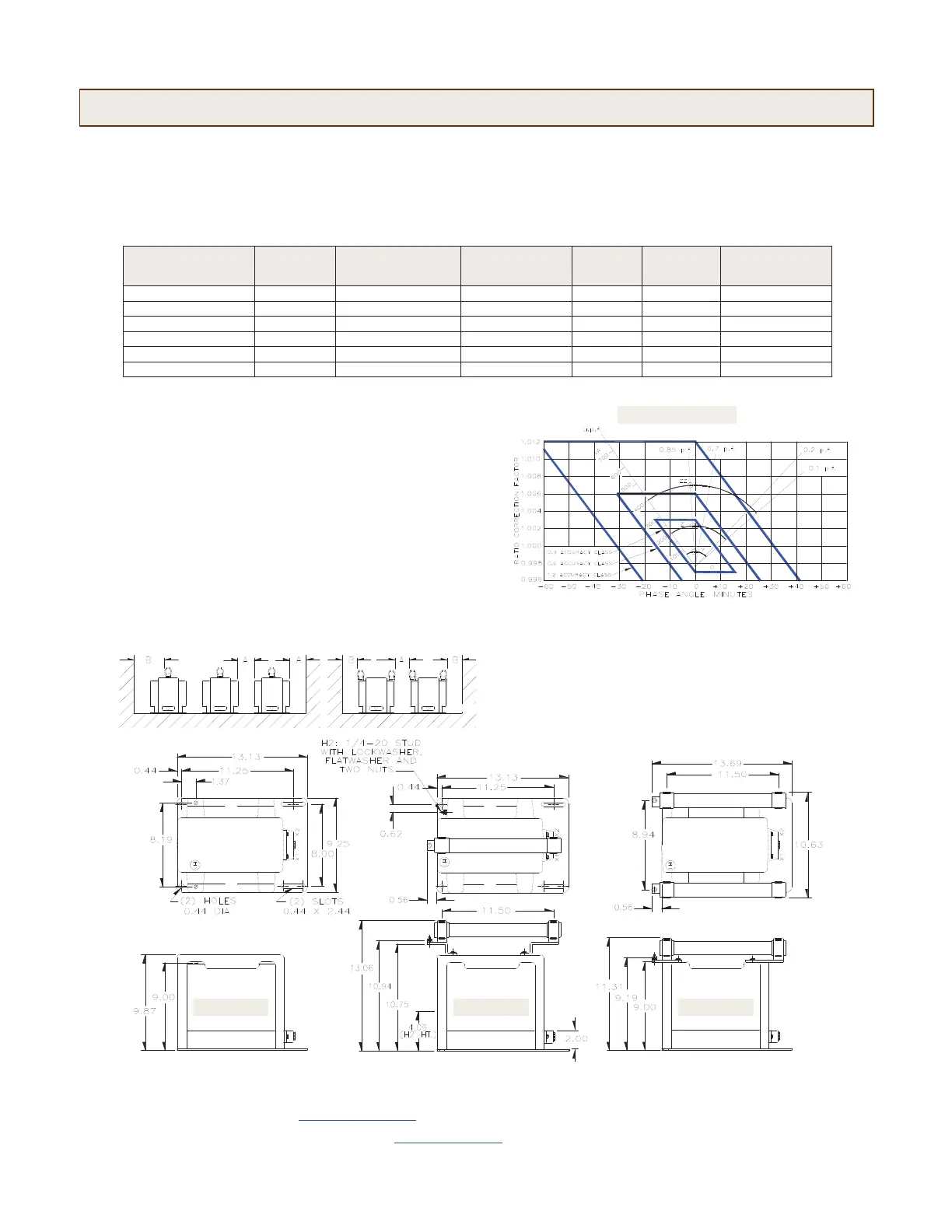
The circle diagram can be used to predict the performance of a transformer
for various loads and power factors. A convenient scale of volt-ampere is
shown on the unity power factor line (u.p.f) and commences at the zero or
no-load locus. To use the diagram, measure the known V.A. and scribe an arc
about the “Zero” locus of a length that contains the angle of the burden
power factor. The point at which the arc terminates is the error locus in phase
angle minutes and ratio correction factor.
CIRCLE DIAGRAM
1”X 2” Notch
RECOMMENDED MINIMUM SPACINGS
A = Unit to Unit or to Ground = 1.25” minimum.
B = HV to Ground in air = 6.50” minimum.
Recommended spacing are for guidance only. User needs to set
appropriate values to assure performance for high potential test,
impulse test, high humidity, partial discharge, high altitude, and other
considerations like configuration.
UNFUSED ONE FUSE TWO FUSE
46
CS00A40661 Rev 3 3/12
USA, Canada, Asia, Latin America
Tel: +1-800-547-8629
Fax: +1-905-201-2455
e-mail: sales.multilin@ge.com
Europe, Middle East, Africa
Tel: +34-94-485-88-00
Fax: +34-94-485-88-45
e-mail: gemultilin.euro@ge.com
Please refer to our website www.GEMultilin.com
for more detailed contact informationMedium Voltage
 Loading...