444
FT & RT Test Switches
www.GEDigitalEnergy.com
Non Standard FT Style Switch Selector
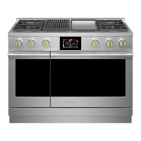
Step 1
through J
Position:
Excample:
Legend:
P=Potential, Black
T=Potential, Red
C=Current, Non-shorting, Black
C-C or C-C-C- or C-C-C-C = Current , Shorting, Black
R = Current, Non-shorting, Red
R-R, R-R-R, R-R-R-R = Current, Shorting, Red
Additional colors available - See page 11
(Note: Some functions will require more than one slot in the
switch body)
Step 2
(Optional)
If a tie bar is required then check this box
and draw a dark heavy line over the poles to be joined.
(In the example shown in Step 1 positions H, I and J will operate
together.)
Step 3
Select a cover style
Clear (installs over open and closed switch blades)
Black (installs over closed switch blades only)
Step 4
Select a rear terminal type
Screws (Standard) Studs (Optional)
P C - - C R C R - - R P P P
FACTORY USE ONLY
Catalog Number Assignment