Terminal Number Opto-input
Terminal 17 Common
Terminal 18 Common
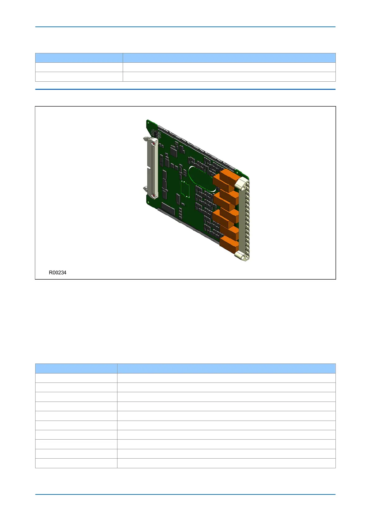
6.6 STANDARD OUTPUT RELAY BOARD
Figure 20: Standard output relay board - 8 contacts
This output r
elay board has 8 relays with 6 Normally Open contacts and 2 Changeover contacts.
The output relay board is provided together with the power supply board as a complete assembly, or
independently for the purposes of relay output expansion.
There are two cut-out locations in the board. These can be removed to allow power supply components to
protrude when coupling the output relay board to the power supply board. If the output relay board is to be used
independently, these cut-out locations remain intact.
The terminal numbers are as follows:
Terminal Number Output Relay
Terminal 1 Relay 1 NO
Terminal 2 Relay 1 NO
Terminal 3 Relay 2 NO
Terminal 4 Relay 2 NO
Terminal 5 Relay 3 NO
Terminal 6 Relay 3 NO
Terminal 7 Relay 4 NO
Terminal 8 Relay 4 NO
Terminal 9 Relay 5 NO
Terminal 10 Relay 5 NO
P54A/B/C/E Chapter 3 - Hardware Design
P54xMED-TM-EN-1 51