In addition to tripping stages 1 to 4, an Alarm stage is also provided (V/Hz> Alm) for each of the elements. This can
be used to indicate an unhealthy condition.
2.1.1 TIME-DELAYED OVERFLUXING PROTECTION
Protection against damage due to prolonged overfluxing is achieved by using the first overfluxing protection stage
with the IDMT characteristic. The setting flexibility of this element
, by adjustment of the time delay at various V/Hz
values, makes it suitable for various country-specific requirements. The manufacturer of the transformer should be
able to supply information about the short-time over-excitation capabilities, which you can use to determine
appropriate settings for the V/Hz tripping element. This variable time overfluxing protection should be used to trip
the transformer directly.
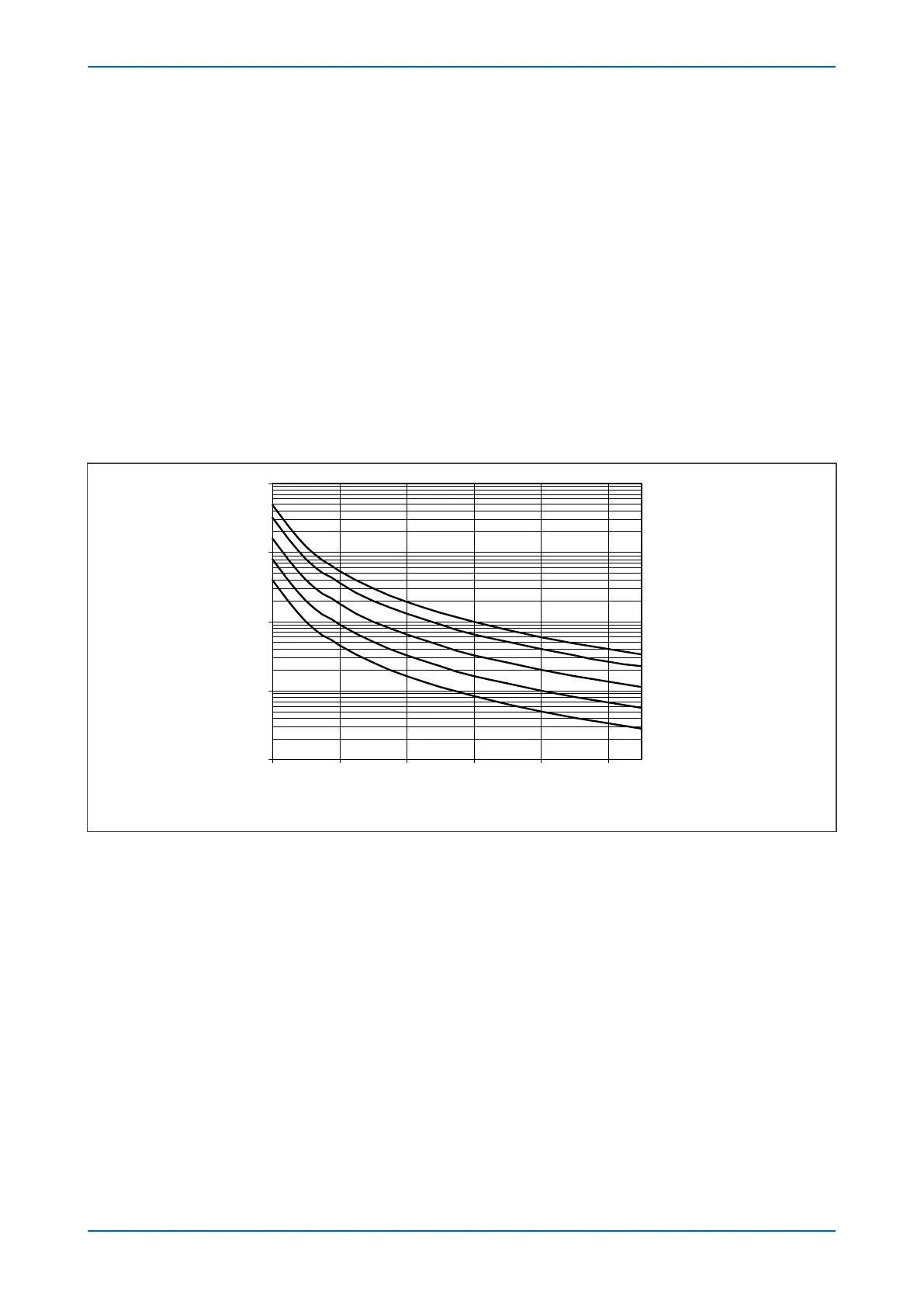
The IDMT characteristic is T = TMS/(M – 1)
2
where:
M = (V/f p.u.) / (V/f trip setting)
V and F are measured entities
TMS = 12
TMS = 8
TMS= 4
TMS = 2
TMS = 1
1
10
100
1000
10000
1.05 1.15 1.25 1.35 1.45 1.55
M = (V/f)/Setting
o
p
e
r
a
t
i
n
g
t
i
m
e
(
s
)
t=TMS/(M-1)
2
V00864
Figure 116: Variable time overfluxing protection characteristic
The IDMT characteristic is implemented as a thermal function. The internal IDMT timer is treated as a thermal
replica with a cooling characteristic. After a V/Hz excursion, the timer should reset according to the reset cooling
characteristic. Otherwise, if the unit is subjected to another V/Hz excursion before it has cooled to normal
condition, damage could occur before the V/Hz trip point is reached.
A linear reset curve with a Reset Time (V/Hz>x tReset) setting is used for this purpose. The actual reset time left is:
Reset time = tReset * IDMTtimer/tTarget
Where tTarget = TMS/(M-1)
2
.
The actual trip time delay is:
Trip delay = tTarget * (1-RESETtimer/tReset)
To make use of the time delayed overfluxing protection, the device must be supplied with a voltage signal which is
representative of the primary system voltage on the source side of the transformer. This is defined by the Ref
Voltage setting in the OVERFLUXING column.
P64x Chapter 12 - Frequency Protection Functions
P64x-TM-EN-1.3 255