– 27 –
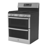
6. Mark and disconnect the 21 wires and wire
harnesses.
7. Remove the 4 Phillips-head screws that attach
the control board to the control panel.
8. Disconnect the wire harness. Remove the two
T-15 Torx screws and six 1/4-in. hex-head
screws from the control panel to remove the
glass touch panel.
Disconnect
To remove the touch panel and ERC (Café models):
1. Remove the cooktop. (See Cooktop.)
2. Remove the 6 Phillips-head screws from the
bottom of the control panel (3 on each side).
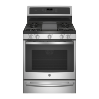
3. Pull the 6 knobs off the control panel.
4. Remove the 7 Phillips-head screws and two T-15
Torx screws holding the control panel to the
burner valves.
(Continued next page)
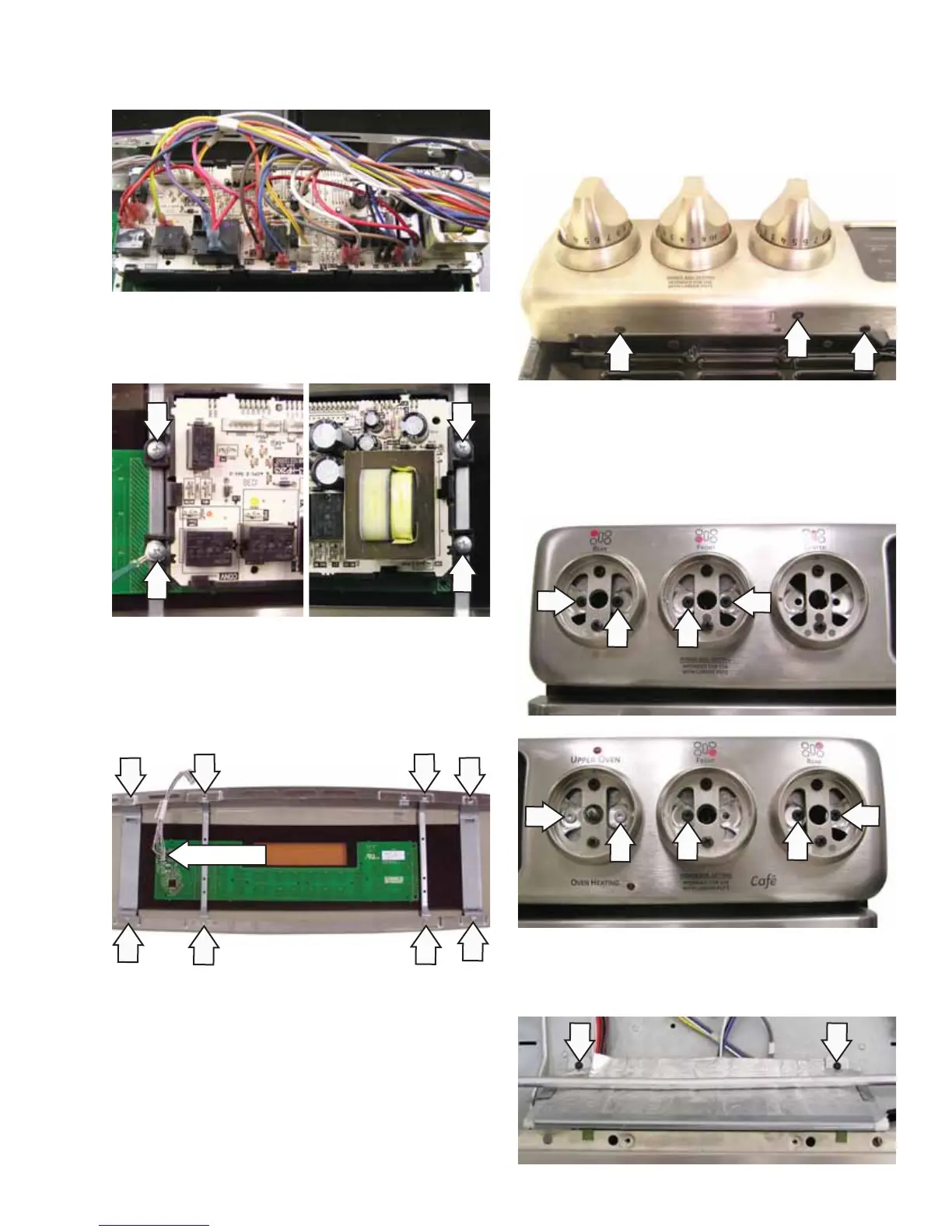
5. Remove the two 1/4-in. hex-head screws and
the heat shield.
 Loading...