EasyManuals Logo

GE Power Break II User Guide

GE Power Break II
27 pages
To Next Page IconTo Next Page
To Previous Page IconTo Previous Page
Page #19 background imageLoading...
Page #19 background image
Power
Break
®
II
Circuit
Breakers
Chapter
3
.
Accessory
Operation
Push
in
this
sides
to
disable
Only
also
change
state
.
The
factory
switch
setting
is
enabled
.
4
.
When
the
Shunt
Trip
accessory
causes
the
breaker
to
trip
,
the
contacts
of
the
Bell
Alarm
with
Lockout
also
change
state
.
The
factory
switch
setting
is
disabled
.
5
.
When
the
Undervoltage
Release
accessory
causes
the
breaker
to
trip
,
the
contacts
of
the
Bell
Alarm
with
Lockout
also
change
state
.
The
factory
switch
setting
is
disabled
.
6
.
When
a
protection
trip
(
long
-
time
,
short
-
time
,
instantaneous
,
or
protective
-
relay
)
occurs
,
the
contacts
of
the
Bell
Alarm
with
Lockout
also
change
state
.
The
factory
switch
setting
is
enabled
.
CD
CJl
^
/
CO
fO
Push
in
/
this
side
to
enable
Rear
of
Trip
Unit
Figure
14
.
Accessory
configuration
switch
on
rear
of
Trip
Unit
showing
factory
settings
(
solid
part
indicates
that
switch
is
pushed
in
on
that
side
)
.
Factory
Setting
Switch
Function
1
Disabled
Shunt
trip
activates
Bell
Alarm
-
Alarm
Only
3
-
8
Motor
Operator
Mechanism
2
Disabled
UVR
trip
activates
Bell
Alarm
-
Alarm
Only
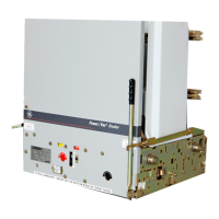
The
Motor
Operator
Mechanism
,
shown
in
Figure
15
,
provides
a
means
of
remotely
or
automatically
charging
the
springs
that
close
the
breaker
.
Table
11
lists
the
catalog
numbers
for
the
available
Motor
Operator
Mechanism
models
.
For
installation
instructions
see
GEH
-
6281
.
Enabled
3
Protection
trip
activates
Bell
Alarm
-
Alarm
Only
4
Disabled
Shunt
trip
activates
Bell
Alarm
with
Lockout
5
Disabled
UVR
trip
activates
Bell
Alarm
with
Lockout
6
Enabled
Protection
trip
activates
Bell
Alarm
with
Lockout
Table
10
.
Accessory
configuration
switch
settings
,
including
factory
defaults
.
Description
of
Switch
Settings
Following
are
descriptions
of
the
effects
of
each
accessory
switch
when
it
is
enabled
:
1
.
When
a
Shunt
Trip
accessory
causes
the
breaker
to
trip
,
the
contacts
of
the
Bell
Alarm
-
Alarm
Only
also
change
state
.
The
factory
switch
setting
is
disabled
.
2
.
When
an
Undervoltage
Release
accessory
causes
the
breaker
to
trip
,
the
contacts
of
the
Bell
Alarm
-
Alarm
Only
also
change
state
.
The
factory
switch
setting
is
disabled
.
3
.
When
the
protection
trip
(
long
-
time
,
short
-
time
,
instantaneous
,
or
protective
-
relay
)
occurs
,
the
contacts
of
the
Bell
Alarm
-
Alarm
Figure
15
.
Motor
Operator
Mechanism
.
12
Courtesy of NationalSwitchgear.com

Other manuals for GE Power Break II

Questions and Answers:

Question and Answer IconNeed help?

Do you have a question about the GE Power Break II and is the answer not in the manual?

GE Power Break II Specifications

General IconGeneral
BrandGE
ModelPower Break II
CategoryCircuit breakers
LanguageEnglish

Related product manuals