OPM_GTU_19X_1K0_3K0_XUS_V014
6
GT-UL Series: User manual 1.2 (US)
Digital Energ
™
GT Serie
g
2.1 Package contents
The packing box contains a Digital Energy™ GT Series-UL UPS, an RS232 data cable, a CD
ROM, two mounting brackets with screws and this manual. Carefully inspect the packing box
and its contents. If any damage is visible please immediately notify the carrier and/or dealer.
2.2 Location
Please refer to section 1.3 of ‘IMPORTANT SAFETY INSTRUCTIONS’
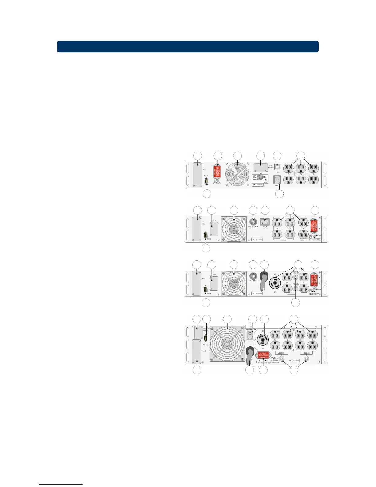
2.3 Rear panel
1
Input
AC utility supply power to the UPS
2
Input breaker
Protects the UPS from damage
caused by high input currents
3
Output receptacles
To connect the critical load to the
UPS
4
Output circuit breaker
Protects the UPS from damage
caused by output overload
5
DC connector
To connect external battery pack
for extended runtime
6
Fan
Electronically controlled cooling
fan. Make sure ventilation air can
move freely around and trough the
UPS.
7
Communication interface
RS232/dry contact. Allows
communication between computer
and UPS. See chapter 4 for more
detailed information.
8 TVSS
-
T
ransient
V
oltage
S
urge
Suppressor (RJ-45/RJ-11): To
prevent damage caused by surges,
noise and spikes traveling over the
telephone or network line.
(Optional)
9
SNMP Slot
An (optional) SNMP adapter can be
plugged into this port for managing
the UPS via the network. See
chapter 4 for more detailed
information.
956
71
82 3
3 51 2689
7
9 8 6 2 1 3 5
4
7
8 7 6 2 8 3
4 5 19
1000VA
1500VA
2200VA
3000VA
Fig 2.1 Rear panels
2 - Installation