– 64 –
Blower Assembly
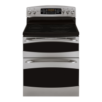
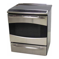
Model PS978
A blower assembly is located under the cooktop at
the back of the range. The blower motor operates
on 120 VAC and has an approximate resistance
value of 58 .
To remove the blower assembly:
1. Remove the rear cover. (See Rear Cover.)
2. Remove the cooktop. (See
Cooktop Assembly.)
3. Disconnect the blower motor wire harness.
4. Remove the two 1/4-in. hex-head screws and
the rear vent trim.
5. Remove the two 1/4-in. hex-head screws from
the back of the rear vent.
6. Remove the eight 1/4-in. hex-head screws from
the rear vent. Lift and remove the rear vent.
7. Remove the four 1/4-in. hex-head screws that
attach the blower assembly to the rear vent.
Disconnect
Thermal Cut Out (TCO) Switch
Model PS978
In the event of an over-heat condition, the thermal
cut out switch will open at 302°F
and disconnect
L2 voltage from the bake, broil, and convection
elements. The switch is non-resetable.
The thermal cut out switch is located to the left of
the RPSM and attached to the back of the range
frame with two 1/4-in. hex-head screws. (See
Component Locator Views.) It is necessary to remove
the rear cover to access the thermal cut out switch.
(See
Rear Cover.)
Note: Before replacing the thermal cut out switch, it
is important to mark the location of the 4 wires that
are attached.
 Loading...