– 31 –
The evaporator fan is the same fan used on previous
models; however, a signifi cant difference is that the
main control board neither requires nor receives
input from the fan feedback/rpm (blue) wire. The fan
utilizes a permanent magnet, 4-pole, DC motor that
operates at 3 different speeds: high, medium, and
low.
The speed of the fan is controlled by the voltage
output from the main control board (J2 pin 8 to J2
pin 3). Voltage output from the main control board
to the fan is 13.6 VDC; however, to regulate the
speed of the fan, the main control board uses pulse
width modulation.
When operating, voltage is sent in pulses (much like
a duty cycle) as opposed to an uninterrupted fl ow.
This pulsing of 13.6 VDC produces effective voltage
being received at the motor, which is equivalent to a
reduction in voltage.
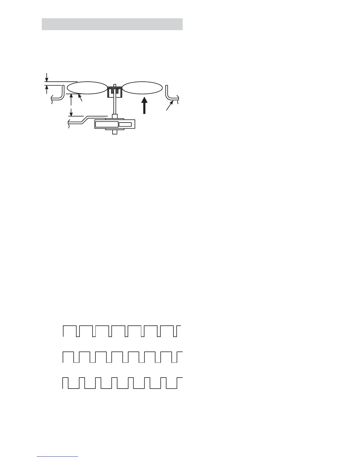
5/16" ± 0.03
Blade tip
1.0" ± 0.05 Target
Motor
Air Flow
Orifice
High Speed (9.5 VDC measured)
Medium Speed (8 VDC measured)
Low Speed (6.5 VDC measured)
9.5 VDC
8 VDC
6.5 VDC
13.6 VDC
0 VDC
0 VDC
0 VDC
13.6 VDC
13.6 VDC
Freezer Evaporator Fan
The position of the fan blade in relation to the
shroud is important.
Fan speed is selected and maintained by the main
control board regulating the length and frequency
of the 13.6-VDC pulse. Temperature can cause
some fan speed variation. Fan speed can vary
+/- 5%, depending on the temperature, with higher
temperatures causing slightly higher speeds.
The evaporator fan has a 4-wire connection:
White Wire - DC Common (J2 pin 3)
The white wire is the DC common wire used
for testing. During repairs, DC polarity must be
observed. Reversing the DC polarity causes a
shorted motor and/or board.
Red Wire - Supply (J2 pin 8)
Each motor uses an internal electronic controller to
operate the motor. Supply voltage from the main
control board remains at a constant 13.6 VDC.
Blue Wire - Feedback/RPM (J2 pin 1)
On previous Arctica models, the blue wire reported
rpm (speed) information to the main control board
for speed control purposes. On this model, the board
does not require or read any feedback information
from the fan motor.
Yellow Wire - Signal (J2 pin 4)
The yellow wire is the input wire from the main
control board. The main control board provides
6.5-VDC effective voltage for low speed, 8-VDC
effective voltage for medium speed, and 9.5-VDC
effective voltage for high speed. The fan operates
in low speed only when the fresh food thermistor is
satisfi ed.
Note: When testing these motors:
• You cannot test with an ohmmeter.
• DC common is not AC common.
• Verify 2 voltage potentials:
a. Red to white - power for internal controller
b. Yellow to white - power for fan
• Observe circuit polarity.
• Motors can be run for short periods using a
9-volt battery. Connect the white wire to the
negative (-) battery terminal only. Connect the
red and yellow wires to the positive (+) battery
terminal.