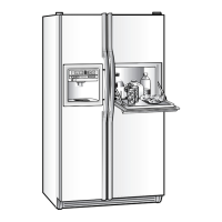
Do you have a question about the GE Profile PSF26PGWBB and is the answer not in the manual?
Key safety warnings and grounding device reconnection instructions are provided.
Explains the ClimateKeeper2 system with two evaporators for optimal temperature and humidity.
Details electrical ratings, temperature controls, and defrost settings for the appliance.
Lists refrigerant charge, compressor capacity, and pressure specifications.
Illustrates the refrigeration cycles for fresh food and freezer sections.
Shows the combined refrigeration cycle for both fresh food and freezer sections.
Provides critical safety precautions for handling refrigerants and using tools.
Details the step-by-step process for evacuating and charging the refrigeration system.
Outlines initial steps for accessing the freezer evaporator, including removing the icemaker.
Continues steps for accessing the freezer evaporator, focusing on the auger motor and fan housing.
Continues steps for accessing the freezer evaporator, involving fan housing, air tunnel, and light bulbs.
Details removing the evaporator cover and related components for freezer evaporator access.
Completes steps for accessing the freezer evaporator, including fan plenum, thermistor, and fan bracket.
Outlines initial steps for accessing the fresh food evaporator, including removing covers and fan cover.
Continues steps for accessing the fresh food evaporator, involving fan disconnection and evaporator removal.
Details the location, resistance values, and removal of thermistors.
Describes the location and access for the freezer evaporator thermistor.
Outlines initial steps for removing the inverter, including disconnecting power and removing the water valve.
Warns about the presence of 120 VAC at the inverter and potential voltmeter limitations.
Explains how the inverter controls compressor speed via frequency and pulse width modulation.
Describes the compressor type, voltage, and wattage, and its control by the inverter.
Details the location, composition, and function of the 3-way valve and its coil.
Describes the components within the valve body and their function.
Explains how the valve coil causes rotation and moves the cam.
Lists components that must be removed to access the CustomCool assembly.
Details steps for accessing the CustomCool assembly, including removing baskets and the fresh food evaporator.
Continues steps for accessing the CustomCool assembly, involving unit removal.
Completes steps for accessing the CustomCool assembly, involving unit orientation and cover removal.
Explains how to use the self-diagnosis mode for testing components via the LCD screen.
Describes the diagnostic aid kit for component testing and its usage.
Details how to enter the diagnostic mode by pressing specific temperature pads.
Outlines various diagnostic tests (Control, Dampers, Fan, Defrost) and their expected results.
Identifies the main control board and lists its connectors.
Lists pin definitions for high-voltage connectors on the main control board.
Lists pin definitions for low-voltage DC connectors on the main control board.
Details the functions and voltage readings for pins on connector J1 of the main control board.
Flowchart to diagnose issues with the Precise Fill water dispensing feature.
| Type | Side-by-Side Refrigerator |
|---|---|
| Brand | GE Profile |
| Model Number | PSF26PGWBB |
| Total Capacity | 25.6 cu. ft. |
| Weight | 320 lbs |
| Color | Black |
| Ice Maker | Yes |
| Water Dispenser | Yes |
| Annual Energy Use | 724 kWh |
| Water Filter | Yes |
| Defrost Type | Frost-Free |
| Height | 69.875 inches |
| Width | 35.75 inches |

