GEH-7299A: Installation, Operation and Maintenance Manual
for Type VR1™ Single-Phase, Step Type Regulators
prolec.energy/prolecge 13
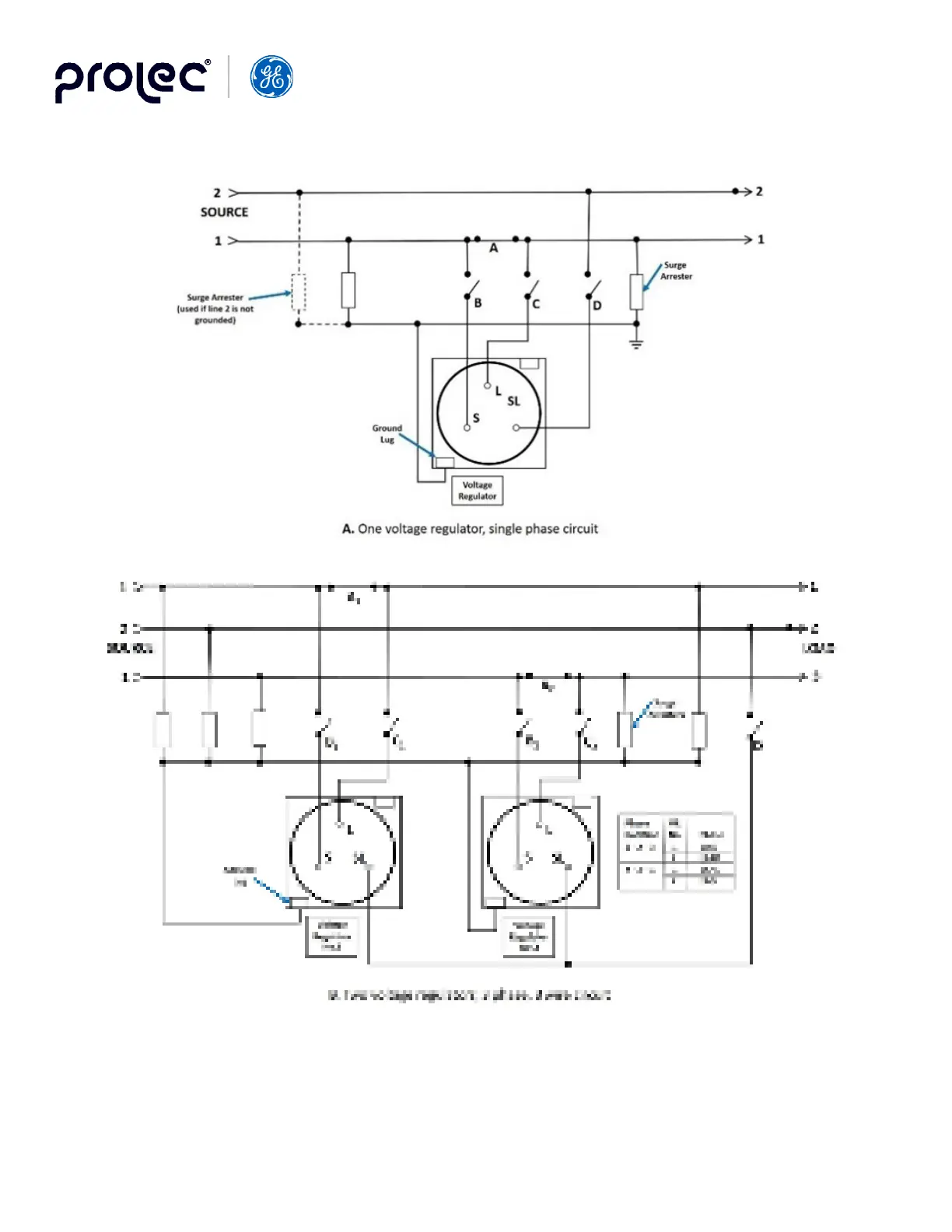
Notes:
1. The control power and Internal-O-External, function (not shown) is located on the regulator control adapter panel. Refer to the control instruction book
for location of the switches detailed in the placing into service and removing from service procedures.
2. Bypass switch “A” and disconnect switches “B”’, “C”, and “D” must be suitable for interrupting magnetizing current.
Figure 6. Regulator Connections (6A & 6B)