GEH-7299A: Installation, Operation and Maintenance Manual
for Type VR1™ Single-Phase, Step Type Regulators
prolec.energy/prolecge 15
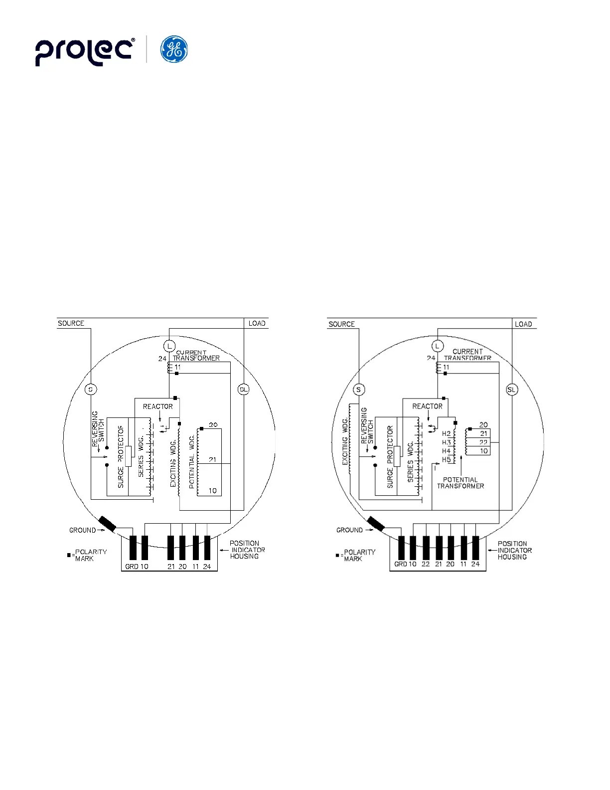
Figure 7. Voltage Regulator Winding Arrangements
Catalog Numbers: 33D7072 through 7720
8050 through 8667
3025, 3050, 3075
4025, 4050
5038
6069
Catalog Numbers: 33D3100 through 3167
4100 through 4333
5076 through 5509
6138, 6274
8833
Figure 7A. Schematic diagram showing connections
of regulator for load excited units
Figure 7B. Schematic diagram showing connections
of regulator for source excited units
For two regulators in an open delta system:
1. Connect the regulators for normal open delta operation. See Figure 6B.
2. Set the motor control switch to AUTO.
3. Set the resistance (R) and reactance (X) adjustments on the line drop compensators of both units to zero.
4. Set the voltage level on each unit to 120 volts.
5. Set “X” on each regulator to 10 volts, leaving “R” on zero. Place the LDC ON/OFF switch to ON. Measure the
output voltages of each regulator after the mechanism has operated to bring the voltage control to a balance
condition (both band and edge indicators are OFF).
6. The regulator with the higher output voltage near the maximum raise position, as observed on the position
indicator, is in the lagging phase; the other is on the leading phase.
For three single-phase regulators connected in a delta bank (Fig. 6D) carrying nearly balanced load and power factor of better
than 80 percent, proceed with steps 2,3,4, and 5 as described above. If all three regulators raise their voltages, they carry
lagging currents. Otherwise, if all three regulators lower their voltages, they carry leading currents.