GEH-7299A: Installation, Operation and Maintenance Manual
for Type VR1™ Single-Phase, Step Type Regulators
prolec.energy/prolecge
18
3.15.2 Load PT Ratio Test
Regulator must be de-energized and in the Neutral position prior to performing ratio test. Instructions are written for DTR
Model 8510 single-phase tester (3-Phase TTR can also be used however, the test lead color will vary).
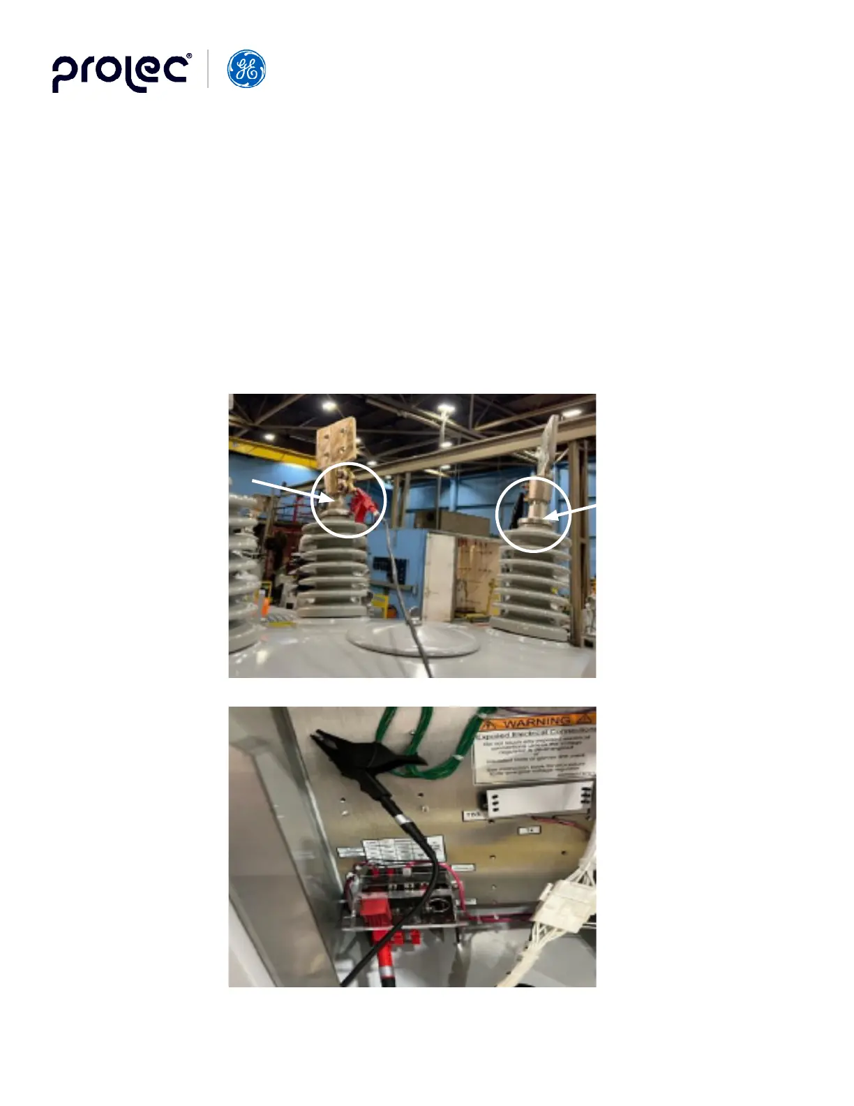
• Connect the red Lead (H1) to the Load (L) bushing, and the black Lead (H2) to the Source-Load (SL) bushing.
• Open the control cabinet door, using the thumb screw, unlatch control module from door jam to access the
knife switches located in bottom left of cabinet.
• Connect black Lead (X2) to Ground stud, and the red Lead (X1) to the top terminal of the knife switch labeled
“Load”.
on the nameplate. For example, if the unit was shipped connected for 7200V, the white pin would be inserted in the hole
adjacent to 7200V on the nameplate and the “Pot Ratio” will be 60:1. (If correct ratio is not obtained, check HV tap setting
inside the tank – refer to Step-Voltage Regulator Nameplate on page 20.
Red Lead (H1)
connection
to Load (L)
Bushing
Black
Lead (H2)
connection to
Source-Load
(SL) Bushing