GEH-7299A: Installation, Operation and Maintenance Manual
for Type VR1™ Single-Phase, Step Type Regulators
prolec.energy/prolecge 25
To operate the mechanism, move the power supply switch to the "OFF" position. This will automatically disconnect the
internal power to the control. Then connect an external power source of 120 volts, 60 HZ to the VOLTAGE IN terminals and
move the power supply switch to the EXTERNAL position. By placing the motor control switch to MANUAL, the mechanism
can now be operated in either the RAISE or LOWER direction. The minimum oil level is indicated in the oil sight gauge.
When retanking the cover-suspended internal assembly, proceed as follows:
1. Rotate the assembly to the approximate tanking position by noting the location of the control housing hold down bolts.
2. After the internal assembly is lowered into place, tap the cover with a rubber hammer around the edge to properly
seal the gasket while tightening the cover band.
3. Bolt the control housing support to the tank wall.
at 25°C (77°F) can be observed through the handhole opening from the indicator side above the cover. Check the dielectric
5.3 Replacing the Internal Clamp Bushing
Release any internal pressure before removing the cover band and bottom control support bolts. Remove the bushing
terminal cap. Lift the regulator internal-and-cover assembly (using the cover lifting eyes) approximately 18 inches.
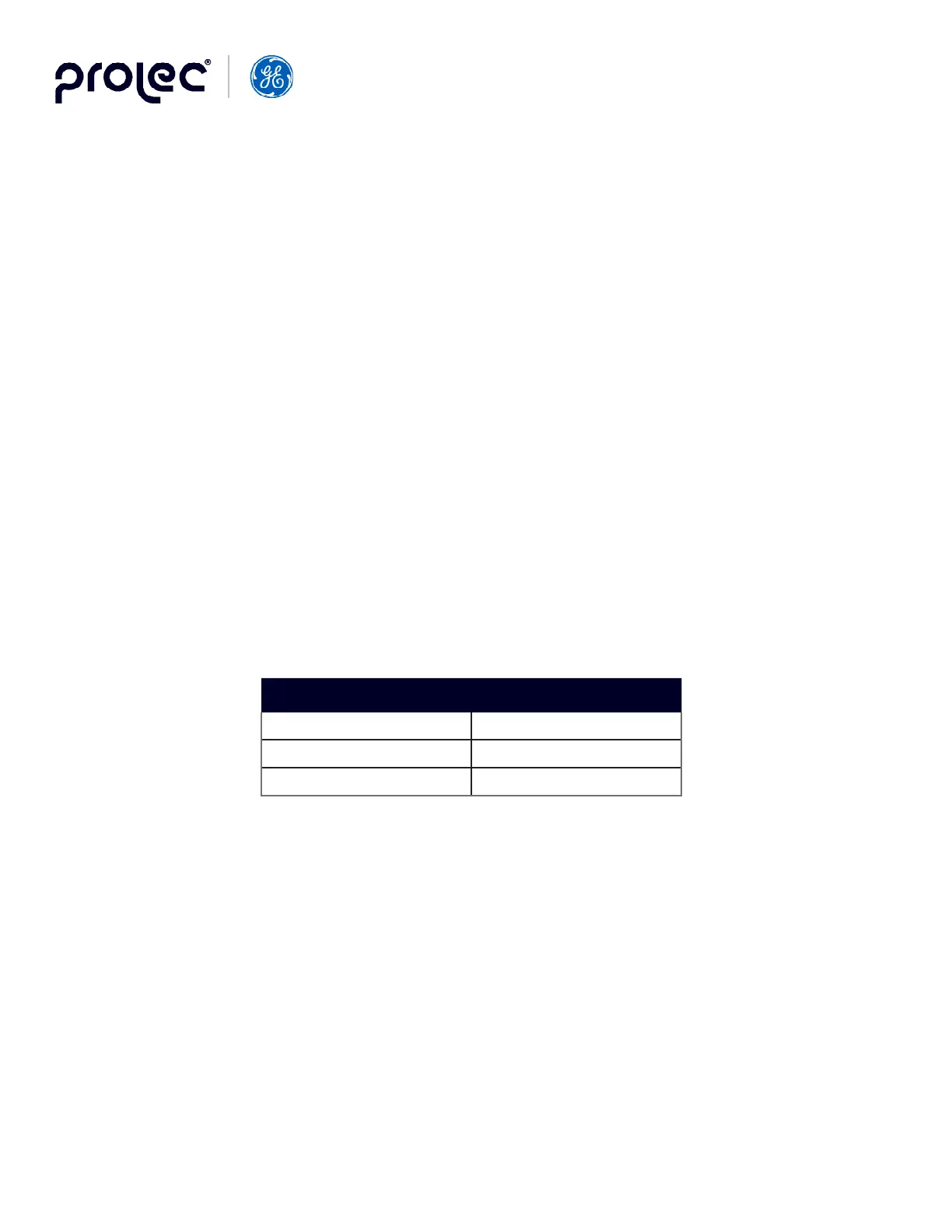
As a safety measure for working under a suspended load, slide a round, steel bar through the large holes in the two upright
angles. The bar length should be long enough to extend several inches beyond the tank rim. The suggested bar diameters
are as follows:
Tank Diameter (In.) Bar Diameter (in.)
19, 21 0.750
24, 25.5 0.875
28 1.00
Table 5. Untanking Support Bar Diameters
Loosen the three screws on the holder and remove the garter spring. The porcelain can then be removed from the cover.
Replace the bushing porcelain, spring, and holder. Torque the screws to 25 - 45 in-lbs. Equalize the torque on all three
screws.