GEH-7299A: Installation, Operation and Maintenance Manual
for Type VR1™ Single-Phase, Step Type Regulators
prolec.energy/prolecge 9
4. Using the UP, DOWN and ENTER buttons: press the UP button until the display indicates ‘BIAS VOLTAGE’
– TEST MODE – Press the ENTER button. Press the UP button to simulate increasing the voltage input until the
LOWER indicator LED comes on. After a couple tap changes, place the MOTOR CONTROL switch to AUTO and
after the time delay expires the regulator should then start operating to lower the voltage. Return the MOTOR
CONTROL switch to MANUAL. Press the DOWN button to simulate increasing the voltage input until the RAISE
indicator comes on. Place the MOTOR CONTROL switch to AUTO and after the time delay expires the regulator
should then start operating to lower the voltage. After a couple tap changes, place the MOTOR CONTROL switch
to MANUAL.
5. Press the ENTER button to cancel the BIAS VOLTAGE and return to the BIAS VOLTAGE screen in the menu.
6. Place the Motor control switch in the “MANUAL” position and engage the Raise/Lower switch to the “LOWER”
position and run the Regulator to the Neutral position.
7. Once the Regulator reaches the Neutral position, the Neutral Light on the adapter panel will illuminate. The yellow
pointer on the position indicator should point to “0”.
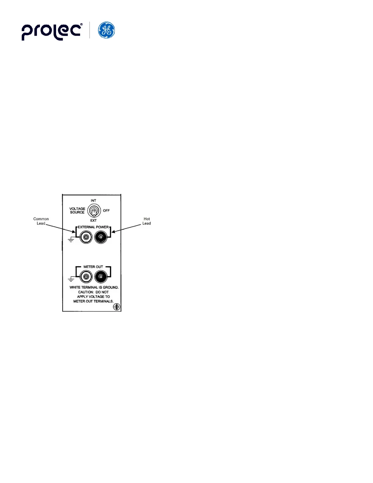
3.3 Exciting the Regulator High Voltage Windings from an External Supply
If it is desired to test the regulator internally in all positions with
an external high voltage power supply, an exciting transformer
of suitable size should be used. When a transformer with too low
kVA rating is used, a noticeable voltage drop may occur in the
supply circuit for odd-numbered positions of the regulator. This
is caused by the additional exciting current required to excite the
reactor in the bridging position. This voltage drop does not indicate
any fault within the regulator. If a small exciting transformer must
be used as a source of voltage, the correct ratio can be obtained by
simultaneously reading the input and output voltage. For checking
the voltage ratio, excite the S-SL bushing with 120 volts. Read the
output on the L-SL. The exciting current at this level will not cause
regulation of the supply.
3.4 Mounting
Mount the regulator on a pole or platform. If the control cabinet is to be separately mounted, run control cable between
the indicator plug and the control cabinet. A kit is available for mounting the control cabinet at the base of the pole. For
information, consult your Prolec GE representative or GE account manager.
Regulators can be connected into a live circuit if suitable devices, as indicated in Fig. 5, are in the circuit. If they are not
provided, de-energize the line before proceeding with the installation.
Thoroughly ground the regulator tank. If the control cabinet is mounted separately, ground it by means of the cabinet ground
porcelain.
Figure 2. GE 2011 External Power

 Loading...


