GEH-7299A: Installation, Operation and Maintenance Manual
for Type VR1™ Single-Phase, Step Type Regulators
prolec.energy/prolecge
10
Some installation requirements may necessitate inversion of the standard mounting brackets, which will increase the
clearance where necessary. The weld-nuts on the tank are spaced to accept either an EEI-NEMA bracket or a bracket for
transformer-mounted arresters.
If the arresters are not mounted on the regulator, they should be installed within 10 feet (3.05 meters) of the regulator and the
ground of the arrester should be connected directly to the ground lug of the regulator tank.
Additional protection against line surges is provided by
ZENOX by-pass protectors, which are mounted inside the
tank and connected in parallel with the series windings.
Notes:
1. The three bypass cutouts are mounted on the side of the crossarm toward
the installation for clarity of the illustration. Mount these bypass cutouts on
the opposite side of the crossarm with the same line connections as shown.
2. Tie surge arrester grounds together and connect to tank ground lug.
Figure 4. Typical Three-Phase Installation
Regular Voltage Class
(kv-rms)
Minimum Suggested
Clearance (mm)
2.5 4 in. (102 mm)
5.0 5 in. (217 mm)
7.62 6 in. (153 mm)
13.8 6 in.(153 mm)
14.4 9.5 in. (242 mm)
20.0 9.5 in. (242 mm)
Table 2. Surge Arrester Clearances
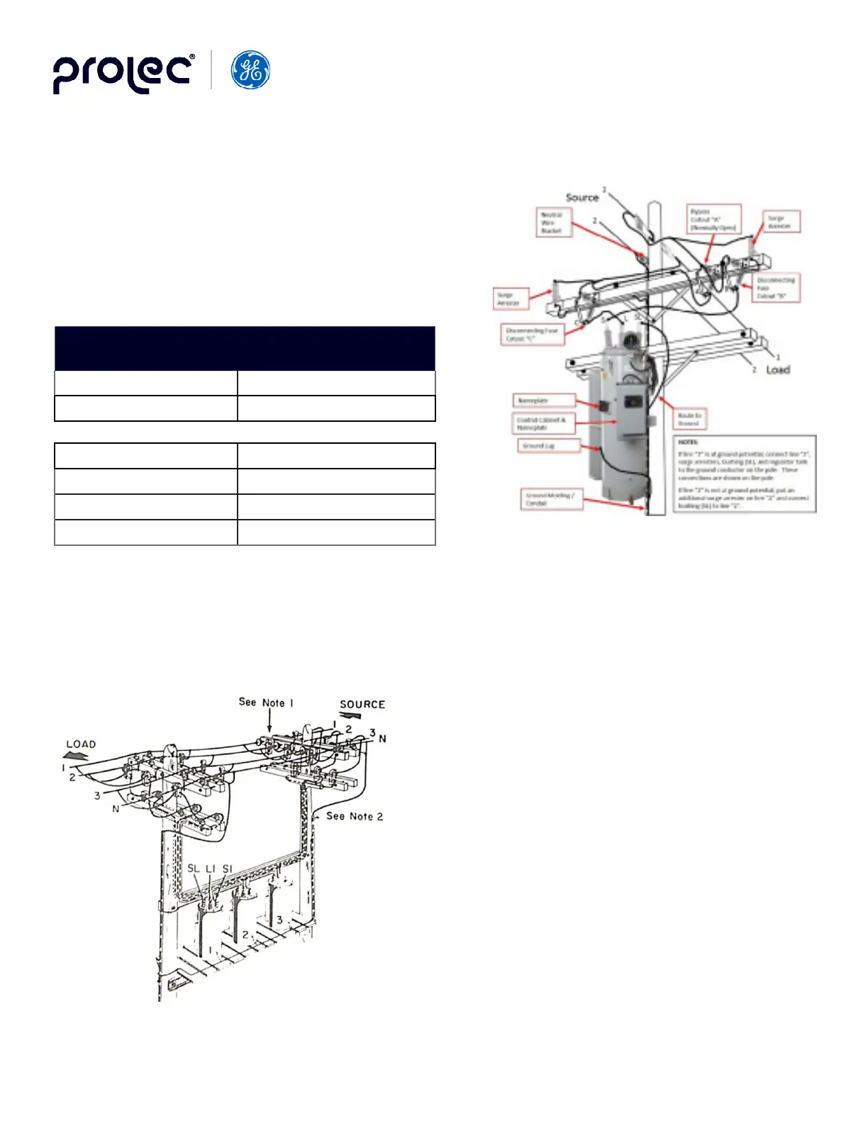
3.5 Surge Protection
Prolec distribution surge arresters (Figure 4.) should be mounted on
the source and load side of the regulator to provide the clearance
values listed in Table 1. The chart indicates the minimum suggested
strike clearance from the line clamp of the arrester to the nearest
ground metal. For proper arrester rating, refer to NEMA-LAI-1965,
Appendix A, “Selection of Arrester Rating”.
Figure 3. Typical SIngle-Phase Installation