– 66 –
Cooktop Components - PSH925
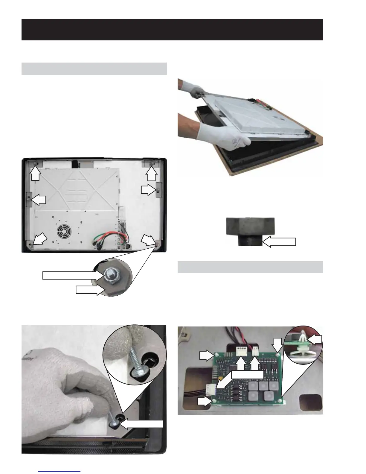
5. Lift the aluminum plate from the cooktop.
Note: When installing the aluminum plate to the
cooktop, be sure to install spacers with the shoulder
toward cooktop.
Shoulder
Bridge Board
The bridge board is located under the cooktop and
attached to the aluminum plate with 4 compression
pins. Three wire harnesses are connected to the
board. It is necessary to remove the aluminum plate
to access the bridge board. (See
Aluminum Plate.)
Disconnect
Aluminum Plate
To remove the aluminum plate:
1. Remove the cooktop assembly. (See Cooktop
Assembly.)
2. Place the cooktop topside down on a protective
surface.
3. Remove the six 3/8-in. hex-head nuts and
spacers.
4. Slide the 6 carriage bolts out of the keyed slots
in the cooktop.
Carriage Bolt
Spacer
3/8-in. Hex-head Nut
Note: The hot surface indicator LEDs are located on
the bridge board. The LED will be turned on when
the cooktop element is turned on and will remain on
as long as the glass temperature exceeds 150°F.
 Loading...