Do you have a question about the GE PS978ST1SS and is the answer not in the manual?
General safety guidelines for service personnel regarding appliance repair.
Instructions for properly reconnecting grounding devices after service procedures.
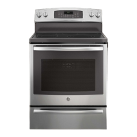
Overview of new features and capabilities for the PHS925 induction range.
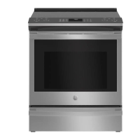
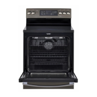
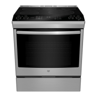
Overview of new features and capabilities for the PS978 radiant range.
Explanation of the alphanumeric code used for identifying the range model.
Guide to decoding the range's serial number for manufacturing date and year.
Visual identification and labeling of key components on the PHS925 front panel.
Visual identification and labeling of key components on the PS978 front panel.
Detailed view of the PHS925 oven and warming drawer internal parts with labels.
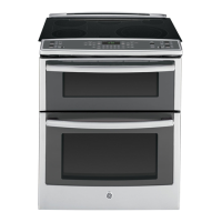
Detailed view of the PS978 upper and lower oven internal parts with labels.
Identification of circuit boards and components within the PHS925 control panel.
Identification of components located on the PHS925 main top surface.
Identification of circuit boards and components within the PS978 control panel.
Identification of components located on the PS978 main top surface.
Diagram showing the arrangement of induction elements on the PHS925 cooktop.
Identification of parts within the PHS925 induction module assembly.
Diagram showing the layout and types of radiant elements on the PS978 cooktop.
Identification of components visible from the rear of the PHS925 range.
Identification of components visible from the rear of the PS978 range.
Diagram and labels for connectors on the PHS925 Relay Power Supply Module (RPSM).
Diagram and labels for connectors on the PHS925 Daughter Relay Module (DRM).
Diagram and labels for connectors on the Main Logic Board for both models.
Diagram and labels for connectors on the PS978 RPSM Main board.
Diagram and labels for connectors on the PS978 RPSM Auxiliary board.
Diagram and labels for connectors on PS978 Daughter Relay Module 1.
Diagram and labels for connectors on PS978 Daughter Relay Module 2.
Step-by-step instructions to remove the oven door assembly from the range.
Step-by-step instructions for reinstalling the oven door assembly.
Instructions for removing the inner oven door assembly.
Instructions for replacing the inner oven door assembly.
Notes on the airflow path within the oven door assembly and insulation precautions.
Guidance on properly installing the oven door gasket seal.
Steps for replacing the outer door assembly on PHS925 models.
Instructions for replacing the outer door assembly on PS978 models.
Steps to remove the upper oven door assembly on PS978.
Steps to replace the upper oven door assembly on PS978.
Steps to remove the outer door assembly of the upper oven on PS978.
Steps to replace the outer door assembly of the upper oven on PS978.
Instructions for replacing the inner door of the upper oven on PS978.
Steps to remove and replace the warming drawer assembly.
Instructions for removing and installing the control panel assembly.
Instructions for removing and installing the main logic board.
Steps to remove the glass touch panel from the control panel.
Instructions for removing the cooktop assembly on the PHS925 model.
Continuation of steps for removing the PHS925 cooktop assembly.
Instructions for removing the cooktop assembly on the PS978 model.
Steps to remove the rear cover on the PHS925.
Steps to remove the rear cover on the PS978.
Detailed steps for removing the left side panel on PHS925.
Further steps for removing the PHS925 left side panel.
Information on disengaging grommets for PHS925 left panel removal.
Instructions for removing the left side panel on PS978.
Further steps for removing the PS978 left side panel.
Detailed steps for removing the right side panel on PHS925.
Further steps for removing the PHS925 right side panel.
Information on disengaging grommets for PHS925 right panel removal.
Instructions for removing the right side panel on PS978.
Steps to remove the oven door hinge receiver on PHS925.
Steps to remove the lower oven door hinge receiver on PS978.
Instructions for removing the RPSM on PHS925.
Instructions for removing the RPSM Main Board on PS978.
Instructions for removing the Daughter Relay Module on PHS925.
Instructions for removing Daughter Relay Module 1 on PS978.
Instructions for removing Daughter Relay Module 2 on PS978.
Steps to remove the oven temperature sensor.
Instructions for removing the broil element on PHS925.
Instructions for removing the broil element on PS978.
Steps to remove the convection fan cover.
Instructions for removing the convection bake element.
Steps to remove the convection fan and motor assembly.
Instructions for removing the bake element on PHS925.
Further steps for removing the PHS925 bake element.
Final steps for removing the PHS925 bake element.
Instructions for removing the bake element on PS978.
Steps to remove and replace the meat probe outlet.
Steps to remove the smoke eliminator and vent tube on PHS925.
Steps to remove the lower oven smoke eliminator and vent tube on PS978.
Steps to remove the upper oven vent tube and smoke eliminator on PS978.
Steps to remove the oven light assembly on PHS925.
Steps to remove the upper oven, right-side, light assembly on PS978.
Steps to remove the upper oven, left-side, light assembly on PS978.
Instructions for removing the oven door switch.
Description of the motorized door lock assembly and its operation.
Information on how the display indicates lock status and operation.
Guidance on testing door lock switches and motor resistance.
Steps to remove the oven door lock assembly on PHS925.
Wiring diagrams for locked and unlocked states of PS978 door locks.
Instructions for removing the upper oven door lock assembly on PS978.
Detailed steps to remove the upper oven liner on PS978.
Final steps for removing the PS978 upper oven liner.
Steps to replace the high limit thermostat on PHS925.
Instructions for replacing the cooling fan and FAD on PHS925.
Steps to remove the cooling fan assembly on PHS925.
Instructions for removing the warming drawer element.
Steps to remove the blower assembly on PS978.
Information on locating and replacing the thermal cut out switch.
Instructions for replacing the bake thermal switch on PS978.
Instructions for replacing the clean thermal switch on PS978.
Steps to remove the aluminum plate from the PHS925 cooktop.
Information about the bridge board's location and function on PHS925.
Detailed steps for removing induction elements on PHS925.
Steps to remove the warming zone element on PHS925.
Precautions and tool usage for removing LINbus connectors.
Explanation of the LINbus master/slave communication system.
Steps to remove the induction module.
Description of the thermal cut out's role in preventing generator board overheating.
Instructions for removing generator boards.
Steps to remove the main filter board.
Details on the construction and operation of radiant heating elements.
Table of wattage and resistance ratings for PS978 surface elements.
Steps to remove the hot surface indicator light assembly.
How to access and interpret error codes displayed on the oven controls.
Detailed steps for accessing and viewing stored error codes.
Procedure to clear displayed error code logs.
Meaning of the 'bAd LinE' display message.
List of oven failure codes, meanings, and corrections.
List of oven failure codes, meanings, and corrections.
List of oven failure codes, meanings, and corrections.
List of induction failure codes, meanings, and corrections.
Procedure to enter the diagnostic test mode.
Table detailing keys, displayed values, and performed tests.
Table listing fan issues, possible causes, and corrective actions.
Detailed wiring schematic for the PHS925ST1SS model.
Key for wire colors and list of components used in the PHS925 wiring diagram.
Detailed wiring schematic for the PS978ST1SS model.
Wire color key and element ratings for the PS978 wiring diagram.
Information on what the warranty covers and does not cover.
Details on warranty exclusions, implied warranties, and consumer legal rights.
| Brand | GE |
|---|---|
| Model | PS978ST1SS |
| Type | Slide-In |
| Fuel Type | Electric |
| Cooktop Type | Induction |
| Number of Burners | 5 |
| Oven Type | Single |
| Oven Capacity | 5.3 cu. ft. |
| Self-Cleaning | Yes |
| Convection Oven | Yes |
| Wi-Fi Connectivity | Yes |
| Color | Stainless Steel |
| Cooktop Surface | Ceramic Glass |
| Width | 30 inches |