
A
Alfred WilliamsJul 29, 2025
What does the Prechill Test do on a GE PSH23PGR Refrigerator?
- NNicholas CampbellJul 30, 2025
The Prechill Test starts Prechill mode. The unit returns to normal on its own.
What does the Prechill Test do on a GE PSH23PGR Refrigerator?
The Prechill Test starts Prechill mode. The unit returns to normal on its own.
What does 100% Run Time mean for my GE PSH23PGR?
The sealed system is running 100% of the time. It times out after 1 hour.
How do the Dampers Test work on a GE PSH23PGR?
The double damper will open, close after 10 seconds, pause briefly, then the single damper will open for 10 seconds.
What does the Duct Door Test do on a GE Refrigerator?
The Duct Door Test opens the dispenser duct door for 10 seconds, then closes it.
What is the Control and Sensor System Test on my GE PSH23PGR?
The Control and Sensor System Test checks each thermistor and displays "P" for pass and "0" for fail.
What does 'F' mean during the Communication check between Dispenser Control and Main Control on a GE Refrigerator?
During the Communication check between Dispenser Control and Main Control, "P" on the freezer display indicates that everything is OK, while "F" indicates a problem.
What does 'F' mean during the Communication check between Temperature Control and Main Control on a GE PSH23PGR Refrigerator?
During the Communication check between Temperature Control and Main Control, "P" on the freezer display indicates that everything is OK, while "F" indicates a problem.
Explains the system components of the CustomCool feature.
Details the operational steps for the CustomCool feature.
Describes the mechanism of the TurboCool function.
Outlines the procedure for using TurboCool.
Controls the dispenser illumination and its automatic activation.
Speeds up ice production for a limited time.
Alerts if refrigerator doors are left open too long.
Secures the dispenser and control panel from unintended use.
Explains selecting and dispensing ice cube or crushed ice.
Details the lock function and its indicators.
Identifies major components located on the rear of the unit.
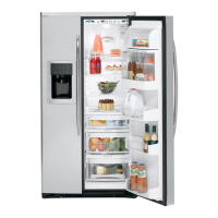
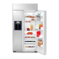
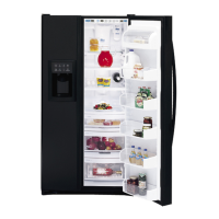
Identifies major components inside the refrigerator compartments.
Illustrates the main control board and its connector layout.
Diagram and explanation of the cooling process for the fresh food section.
Diagram and explanation of the cooling process for the freezer section.
Diagram showing simultaneous cooling of both sections.
Resistance values and location of FF and FZ thermistors.
Describes the forced air defrost method for the fresh food evaporator.
Explains the extended defrost cycle for frost buildup.
Details the second stage of extended defrost.
Describes the forced defrost triggered by cooling time.
Explains the defrost cycle for the freezer evaporator using a heater.
Details the electrical resistance and function of the 3-way valve coil.
Describes the internal components and refrigerant flow in the valve body.
Explains how coil pulses cause magnet rotation and cam movement.
Procedure to test valve movement upon power reconnection.
Details the parts and process for replacing the 3-way valve.
Explains how to enter diagnostic mode and interpret test results.
| Brand | GE |
|---|---|
| Model Series | PSH23PGR |
| Category | Refrigerator |
| Type | Side-by-Side |
| Refrigerator Capacity | 14.6 cu. ft. |
| Ice Maker | Yes |
| Water Dispenser | Yes |
| Defrost Type | Frost-Free |
| Energy Star Rated | Yes |
| Height | 69.5 in |
| Color | Stainless Steel |