EasyManua.ls Logo

GE SPUV480AC - User Manual

GE SPUV480AC
4 pages
Print Icon
To Next Page IconTo Next Page
Loading...
Catalog
Number
Voltage
Rating
Peak Inrush
Current, mA
Nominal RMS
Current, mA
SPUV480AC
480 Vac
750 20
SPUV600AC
600 Vac 600
16
Rated for 50/60 Hz. Rating is 120 Vac without step-down
transformer.
Peak inrush current is present for 2–6 ms after activation. This
number is provided so that fuses and supplies can be chosen
appropriately.
AVERTISSEMENT:
Les modules de déclenchement à
manque de tension 480 Vac et 600 Vac doivent être
utilisés avec le transformateur abaisseur de tension qui
est fourni.
When the applied control voltage is above 80% of the UVR’s
rated value, th e breaker can be closed. When the voltage
drops to 35–60% of the rated value, the UVR will trip the
breaker.
The Undervoltage Release is installed in the accessory
compartment through the front of the circuit breaker in the
position shown in Figure 2.
Use the following procedure to install the UVR accessory into
the UVR slot in the accessory compartment of the circuit
breaker:
Open the hinged door over the accessory compartment
and Trip Unit.
To remove an existing accessory, loosen the accessory
locking screw and pull the accessory out with the Rating
Plug Removal Tool (catalog number TRTOOL).
AVERTISSEMENT:
Avant d’installer toute accessoire, mettre
le disjoncteur en position OFF, le déconnecter de toute
tension d’alimentation, et décharger les ressorts
d’armement.
WARNING:
480 Vac and 600 Vac Undervoltage Release
accessories must be used with the supplied step-down
transformer.
WARNING:
Before installing any accessories, turn the
breaker OFF, disconnect it from all voltage sources, and
discharge the charging springs.
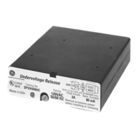
Figure 1. Undervoltage Release.
1
Table 1. Catalog numbers and voltages for the Undervoltage Release.
Installation
GEH6520 I NSTRUCTIONS
Power Break® II Circuit Breaker Accessories
Undervoltage Release 480 & 600 Vac
Introduction
The Undervoltage Release (UVR) accessory, shown in Figure 1,
can be installed in 800–4000 ampere frame Power Break® II
circuit breakers. This accessory trips the circuit breaker when
the input control voltage drops to 35–60% of its rated value
and prevents an open breaker from closing until the input
control voltage is greater than 80% of the rated value.
In addition to providing a trip signal to the breaker, the UVR
accessory can be set up to interact with other Power Break II
accessories, when used with a MicroVersaTrip Plus™ or
MicroVersaTrip PM™ Trip Unit. DIP switches on the rear of
the breaker Trip Unit can configure the UVR accessory to
activate a Bell Alarm–Alarm Only accessory or a Bell Alarm
with Lockout accessory when a UVR trip occurs. The
Accessory Configuration section below describes how this
can be done. If the breaker is equipped with a Power+™ Trip
Unit, it is configured so that only protection trips will activate
a Bell Alarm–Alarm Only or Bell Alarm with Lockout.
The catalog numbers for the UVR for 480 and 600 Vac
applications are listed in Table 1. Voltage and current ratings
in Table 1 are given at the input of the transformer. The
voltage and current ratings at the input of the UVR accessory
are equal to that of the SPUV120AC accessory. Input voltage
is 120 Vac, peak inrush current is 3 A, and the nominal RMS
current is 80 mA.
Operation
Apply control voltage to the primary of the supplied step-
down transformer. The secondary of the transformer is
connected to terminals 29 and 30 of the terminal strip on the
right side of the breaker.
1.
2.
Question and Answer IconNeed help?

Do you have a question about the GE SPUV480AC and is the answer not in the manual?

Overview

The Undervoltage Release (UVR) accessory is designed for installation in 800-4000 ampere frame Power Break® II circuit breakers. Its primary function is to trip the circuit breaker when the input control voltage drops to a range of 35-60% of its rated value. Additionally, it prevents an open breaker from closing until the input control voltage exceeds 80% of the rated value.

Function Description:

The UVR accessory provides a critical safety and operational feature by monitoring the control voltage. When the voltage falls below a specified threshold (35-60% of rated), the UVR initiates a trip, opening the circuit breaker. This prevents operation under potentially damaging low-voltage conditions. Conversely, it ensures that the breaker cannot be closed if the control voltage is insufficient (below 80% of rated), thereby preventing an unstable or incomplete closing operation.

Beyond its core tripping function, the UVR accessory can interact with other Power Break II accessories, specifically when used with a MicroVersaTrip Plus™ or MicroVersaTrip PM™ Trip Unit. DIP switches located on the rear of the breaker's Trip Unit allow for configuration of the UVR accessory to activate a Bell Alarm-Alarm Only accessory or a Bell Alarm with Lockout accessory upon a UVR trip. This provides an audible or visual alert, and potentially a lockout mechanism, in response to a low-voltage condition. If the breaker is equipped with a Power+™ Trip Unit, only protection trips will activate these Bell Alarm accessories, not UVR trips.

Important Technical Specifications:

  • Compatibility: 800-4000 ampere frame Power Break® II circuit breakers.
  • Voltage Ratings: Available for 480 Vac and 600 Vac applications.
  • Input Voltage (at transformer primary): 480 Vac or 600 Vac.
  • Input Voltage (at UVR accessory): 120 Vac (requires a supplied step-down transformer for 480/600 Vac applications).
  • Peak Inrush Current (at UVR accessory): 3 A (present for 2-6 ms after activation).
  • Nominal RMS Current (at UVR accessory): 80 mA.
  • Frequency: Rated for 50/60 Hz.
  • Trip Threshold: Trips when control voltage drops to 35-60% of rated value.
  • Closing Inhibition Threshold: Prevents closing until control voltage is greater than 80% of rated value.

Usage Features:

  • Installation: The UVR accessory is installed in the accessory compartment through the front of the circuit breaker. It is keyed for the correct slot, ensuring proper placement. A locking screw secures the accessory in place.
  • Transformer Requirement: For 480 Vac and 600 Vac applications, the UVR accessory must be used with the supplied step-down transformer. The primary side of the transformer connects to the control voltage, and the secondary side connects to terminals 29 and 30 of the breaker's terminal strip.
  • Configuration with Trip Units:
    • MicroVersaTrip Plus™ / PM™: The UVR can be configured to activate Bell Alarm-Alarm Only or Bell Alarm with Lockout accessories upon a UVR trip. This involves removing the Trip Unit, setting DIP switches on its rear, and reinstalling it. Specific switch settings determine the interaction.
    • Power+™: With a Power+™ Trip Unit, the UVR accessory's trip will not activate Bell Alarm accessories; only protection trips will.
  • Operational Sequence:
    1. Apply control voltage to the primary of the step-down transformer.
    2. The transformer's secondary connects to the breaker's terminal strip.
    3. If applied control voltage is above 80% of the UVR's rated value, the breaker can be closed.
    4. If the voltage drops to 35-60% of the rated value, the UVR will trip the breaker.
  • Safety Warnings:
    • Always turn the breaker OFF, disconnect from all voltage sources, and discharge charging springs before installing any accessories.
    • Over-tightening the locking screw can damage or distort the accessory case.

Maintenance Features:

  • Testing Procedure: A specific procedure is outlined to test the UVR for proper operation:
    1. Open the breaker.
    2. Turn off power to the UVR.
    3. Attempt to manually close the breaker (it should not close).
    4. Apply at least 80% of the rated voltage to the UVR control inputs.
    5. Attempt to close the breaker (it should close normally).
    6. If a MicroVersaTrip Plus or PM Trip Unit is installed, verify its display is active.
    7. With the breaker closed, reduce the UVR control voltage to 35-60% of the rated value; the breaker should trip within 0.5 seconds.
    8. If Bell Alarm accessories are present, ensure they activate (or do not activate) as configured by the Trip Unit DIP switches.
  • Troubleshooting Guide: A comprehensive guide helps diagnose common problems:
    • UVR not inserting completely: Check for incorrect insertion, proper alignment, and tightness of the locking screw.
    • Breaker closing when UVR is de-energized: Verify the UVR lockout plunger protrusion and ensure control power is off.
    • Breaker not closing when UVR is energized: Check if UVR control power is applied above 80% of rated voltage and if the accessory is fully inserted.
    • Breaker not tripping when UVR control power is removed: Verify the breaker is closed, UVR control power is removed or below 35% of rated, and the UVR accessory/Trip Unit are correctly inserted.
    • Bell Alarm accessories not tripping correctly: Check the configuration switches on the Trip Unit (for MicroVersaTrip Plus/PM) and proper installation of the Bell Alarm accessory.
  • Switch Setting Changes: The procedure for changing accessory switch settings involves:
    1. Removing the breaker trim plate and cover.
    2. Pulling out the Trip Unit.
    3. Referring to the switch diagram and table to identify switches to be changed.
    4. Pushing the appropriate "Enable" or "Disable" side of the switch.
    5. Reinstalling the Trip Unit, cover, and trim plate, ensuring proper torque for screws.
    6. Verifying switch settings by inducing breaker trips and checking Bell Alarm responses.

GE SPUV480AC Specifications

General IconGeneral
BrandGE
ModelSPUV480AC
CategoryCircuit breakers
LanguageEnglish

Related product manuals